

| Home | For sale | Site map | Contact information | Guest book | The Panzerschreck Lounge |
 The
Panzerschreck ammunition The
Panzerschreck ammunition |
|---|
A study of types, construction and effect of ammunition The Raketen Panzer Büchse Granat 4322 (winter 43/44 version) as it was pictured in the instructional slide series for the Panzerschreck The Panzerschreck as a weapons-system was entirely dependent on the ammunition for performance. And as the launcher was continually improved, so was the ammunition. At the same time, the ammunition was always the weak point of the Panzerschreck system, all up until the end of hostilities. To better understand the functioning and construction of the grenade I will divide it into its logical parts and describe them separately. Only this way will it be possible to understand the difference between the different models. For those that can't be bothered to read the full text I will give you a shortlist of the different official models right here.
The main parts & function The grenade consisted of 4 main parts, of which (broadly speaking) two and two worked together. The red line below illustrates this.  The igniter was plugged manually into the connector box on the rear end of the launcher. When fired, it would ignite the rocket motor, which in turn would propel the entire grenade forward for 3 meters before it was completely burnt out. The grenade would now have a velocity (V0) of 100 meters per second and would be in "free flight". On impact the fuze would be set off, detonating a small blast cap that would send a "spit-back" to ignite the booster, which in turn would detonate the shaped charge in the back off the warhead that would form a jet that would punch through the armour.  Let's break it down! The Igniter The igniter would use the current produced by the Stoßgenerator to ignite the rocket motor. The igniter consisted of a bakelite plug that was glued into the venturi (jet nozzle). A steel top disk with a crimped edge sealed off the end to make it "weatherproof". The actual electric igniter (Raketenmotoranzünder) protruded from the front of the bakelite plug. One of the wires coming out of the top disk was soldered to the rocket body inside the tail drum. The other wire was soldered to a metal pin placed in the wooden handle. The wooden handle was a square piece of wood with a circular depression on one side on the middle (to avoid damaging the wires). The handle was taped across the rear end of the tail drum where it would protect the igniter during transport. 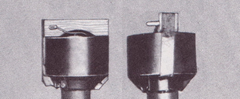 An improved model was introduced with the Wintermunition 1944/45. The wooden handle was reduced in size and form to a tapered design and was repositioned inside the tail drum. 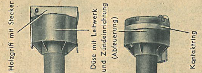 The picture at the right above shows a prototype of the 8,8 cm R Pz B Granate 4992 with the second model igniter handle stored inside the tail drum. This igniter was also used on the 8,8 cm R Pz B Granate 4322 with the Wintermunition 1944/45 motor When the rocket fired, the igniter would be spit out of the rear, and according to the manual D 1864/1 “The ignition device will fly 30 m to the rear." Normally, the wire attached to the wooden handle would snap, and the wooden handle would have to be removed manually before a new could be inserted. 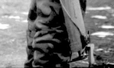 The second model of the grenade, the 8,8 cm R PzB Gr. 4992, had an integrated contact system that made the wooden handle superfluous when the grenade was fired from the 54/1. This system is described in details on the page about the R Pz B 54/1 There is no evidence to support the theory that the second model grenade was ever mass-produced. The Rocket motor The rocket motor was the only difference between the 3 production varieties of the 8,8 cm R PzB Gr. 4332 (apart from the improved wooden handle). The different versions of the motor could be identified by the marking on the motor tube.
The motor consists of a steel tube with a closed front, 40 mm in diameter, with a 2,5 mm thick wall that is threaded in each end. The tail drum is welded to the venturi, which in turn is screwed on at the end and holds the internals of the rocket motor in place. 1. Spacer ring - 2. Grid - 3. Fuel rods - 4. Grid - 5. Black powder charge The above photo is a manipulation to show the construction of the rocket motor and the components The first two models of the motor were identical in construction. Inside the removable venturi the motor has a spacer ring (1) at the very end that holds everything in, and in the right position. In front of this is a grid (2) constructed from 4 pieces of flat iron pressed together. The grid will ensure that the fuel rods don't travel backwards and block the ventiru. There are 7 fuel rods (3), 6 forming a full circle and 1 rod in the centre. The fuel rods are made of Diglycol and are 10,5 mm in diameter and 200 mm long, and have a centre-hole of 6 mm. The central fuel rod has a 6mm celluloid tube inserted that is slightly longer than the fuel rods, which ensures that it rests inside the centre grid in each end (not visible in the picture above). The celluloid tube contains a small black powder pellet in both ends and a thin strip of Diglycol powder between the pellets. In front of the fuel rods another grid (4) holds the central fuel rod in place and ensures that there is sufficient space between the fuel rods and the ignition charge (5). The ignition charge is made of black powder and is held inside an aluminum disk with a celluloid front plate. 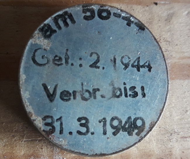 (Picture courtesy of Detlef W.) The aluminum disc that contained the black powder charge. Gefertig (made) in February 1944. Verbrauch bis (use before) April 1949! In order to build up enough pressure to work properly the fuel rods must burn up from the front to the rear. The electrical igniter will set off the small black powder pellet in the celluloid tube placed in the centre fuel rod. The fire will then travel inside the rod until it reaches the black powder pellet in the other end, which will in turn set off the ignition charge. This will be sufficiently strong to ignite all 7 rods at once, which in turn will burn up and become gas. The gas escaping through the venturi will in turn push the rocket forward. In recoil-weapons, like a howitzer or a mortar, the pressure acquired from a propelling charge is built up behind the projectile, and held by the barrel-walls. The Panzerschreck motor would have to be strong enough to contain all the gases on the inside and only permit them to exit through the venturi. This was one of the Panzerschrecks weak points! High-pressure meant better accuracy and performance. Too high pressure would result in a burst motor and subsequently a destroyed launcher with injury to personnel. 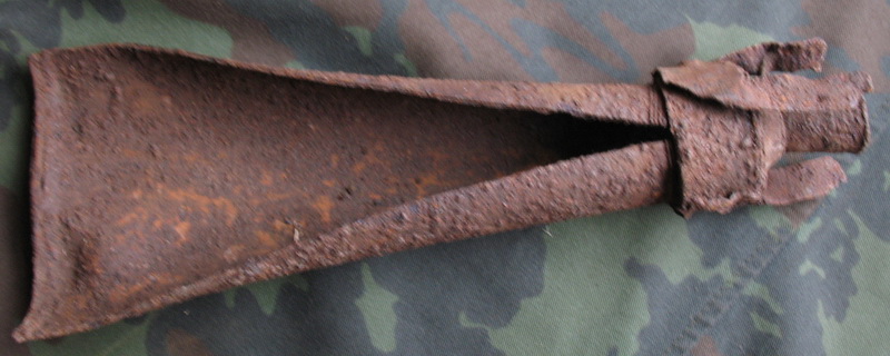 This picture shows what happens to the motor when the built up pressure is more than it is constructed for. This one was dug up in the former Soviet Union All ammunition faces the same problem. The hotter the powder - the higher the pressure - different ballistics. The warmer the rocket motor was initially, the higher the pressure got when it ignited! In the operator manual it was advised to keep the ammunition stored in heated bunkers in the wintertime until it was needed. This gave a much better hit probability. A grenade that had been overheated (reached a temperature above the allowed temperature range, for example due to direct sunlight exposure) would be unsafe to fire. The grenade could be used again, once it had cooled down to the certified temperature range. 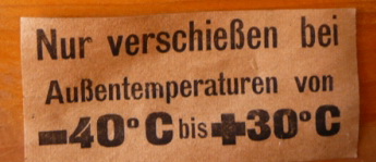 Warning label on a box of "Wintermunition 1943/44". On a bad day, a grenade left in the sun for some time would blow up when fired! The first 15.000 grenades manufactured had to be restricted to use between -10 and +30 degrees C. (These were not meant for operational use, so correct "type or designation" for this ammunition is not known). The first production ammunition was the "Wintermunition 1943/44". This was certified for use between -40 and +30 degrees C, and was marked "Arkt" (Arctic/winter) on the motor. The next version was the "Sommermunition 1944" that was certified for use between -5 and +50 degrees C. This ammunition had no special marking on the motor. The difference between the first two production models appears to be the composition of the fuel rods. The last production version was
the "Wintermunition 1944/45" which was marked "Arkt
44/45" on the motor tube. This motor was certified for use
between -25 and +25 degrees C. Although the temperature range
was just as
limited as earlier models, this version had
improved performance and would
now be useable out to 200 meters. (This version also introduced the new
wooden
handle for the igniter). The internals of the motor was redesigned after the two first models. The 7 fuel rods were replaced with one single stick. This was moulded in the form of a “spoke wheel” with one central tube (the axis) surrounded by 14 channels. This gave a maximum of surface area and low thickness of the fuel, to ensure the best possible contact with air for the combustion process. The ignition charge at the top of the tube appears to have been considerably increased in size as well, and replaced the upper grid. 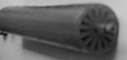 This is the only known picture of the propellant stick for the Arkt 44/45 motor. The "spoke wheel" design and the central igniter tube are both visible The new design would give a
more efficient combustion, resulting in a higher V0 (Velocity
at the
starting point). With a higher V0, the grenade
would go further with
better accuracy, and if the combustion of the motor was completed
before the
grenade left the launcher it would be possible to discontinue using the
shield. It seems
unlikely that this was achieved with the Wintermunition 1944/45, but
the
introduction of the grenade offered an increased combat range resulting
in a new front
sight. This sight has been described in detail on the page about the sights.
When the rocket motor had burnt out it was all down to free-flight and the fuze. The fuze used on the Panzerschreck Granate was the AZ 5095/1 (Aufschlagszünder 5095/1). This fuze was not very well suited for the grenade, but was the only model used for the duration of production. The AZ 5095/1 was issued with a manual safety pin with a hole in the end for a wire & lead seal. Due to the construction of the fuze it was vitally important that the safety pin had an intact seal! If ammunition was received without the safety pin in place, or even just missing the lead seal, it was not judged as safe and should under no circumstance be handled or used.
A document issued as an annex to the Heerestechnisches Verordnungsblatt in August 1944 mentions the trouble with the safety. "All Panzerschreck grenades found with a missing lead seal, no matter what cause, is not judged as safe to use and should be destroyed by technical personnel." 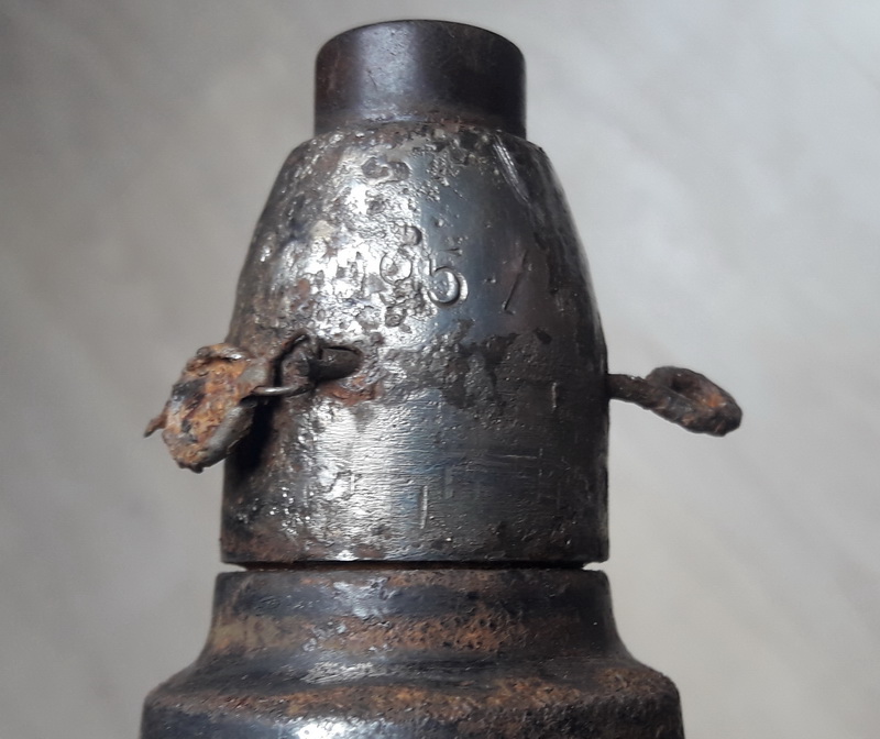 (Picture courtesy of Detlef W.) An Aufschlagszünder 5095/1 fuze with the safety pin and the lead seal intact. Do not handle or use the rockets if this seal is missing! Although only one type of fuze was used with the production grenades other varieties was tried. The problem was first of all the (lacking) safety features. A lot of testing was done to try to utilize a base mounted-detonator (much like the Panzerfaust) based on the Bd. Z. 5142 (Boden Zünder 5142). It was renamed twice, and ended up as A.Z.J.M.12 on 4. February 1945. This was the final approval from the WaA for use with the Panzerschreck grenade, and all production drawings were ready. It is doubtful that it ever made it to production though. The Warhead The actual warhead was a
classical shaped charge. The front portion of the head was hollow with
the fuze
mounted in front at the correct “stand-off” length required to get the
maximum
effect from the explosive charge. The rear end of the warhead held the
explosives inside an inverted bottle-shaped liner. The liner had a hole
in the
bottom to allow the “spit-back” from the detonator in the fuze to hit
the
booster that was embedded in the explosives. The booster was the Kleine
Zündladung 34. A wooden dowel was inserted in the very end of the
warhead and
acted as a thermal insulation between the rocket motor and the booster.
The shaped charge would focus
the enormous pressure from the explosive’s energy on the liner, driving
this
inward so that it collapses on its central axis. The result is a
collision that
forms and projects a jet of metal particles from the liner that moves
forward
along the axis at 7000 meters per second. The extended nose section of
the 4322
gives the correct stand-off distance. This allows the detonation to
fully build
up the kinetic energy enabling the jet to deliver its punch with
maximum effect
against the armour. If the grenade is set off before it hits the actual
armour
the effect will be less effective. The jet would punch a hole in the
armour
that was considerably smaller in diameter than the 8,8 cm of the
grenade, but
the size of the impact hole had no relation to the effect of the
grenade on the
other side of the armour. The actual jet would be dispersing even as it
went
through the armour, leaving a wider hole on the inside. This added to
the
effect of the punch, as particles (and parts) of the armour would be
torn off
on the inside and act as projectiles inside the tank. In addition the
heat and pressure from
the jet would set off ammunition and wound or kill the crew. The
Panzerbeschußtafel 25 describes the effect as follows:
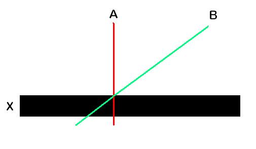 X represents the armour plate. A is a grenade with a 90 degree impact and B represents a grenade with a 45 degree impact. Grenade B will have to punch through a considerable thicker piece of steel than grenade A. The 8,8 cm R Pz B Gr 4322 would penetrate 17 cm of armour, more than enough to knock out all known Allied tanks. The important part was to hit the hull or tower, and not external parts like the road wheels, tracks etc. The effect of the grenade against other targets would be very limited and the manuals clearly advised against it. The D 1864/1 states: Use (the 8,8 cm R PzBGr 4322) only against tanks, due to a low fragmentation effect it is not effective as a high explosive grenade. The ability to penetrate armour is a result of the shaped charge effect. 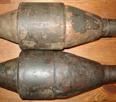 All contemporary German pictures and drawings show grenades of the upper type. In this case the upper is a Arkt 44/45 grenade and the lower is a Arkt grenade. 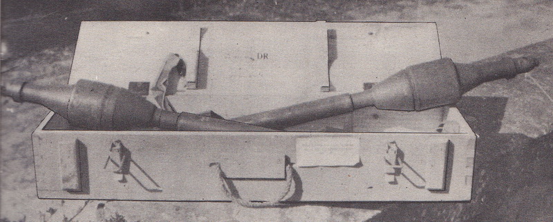 The picture above is from the Recognition handbook for German ammunition, published by the SHAEF in April 1945. Both models of the warhead are visible. The box is for Sommermunition 1944 judged by the unreadable label attached to the front. The explosive used in the warhead was 700 grams of Hexogen and TNT in a 60:40 mix. This mixture had the code number "97", which could be found ink-stamped on the head. 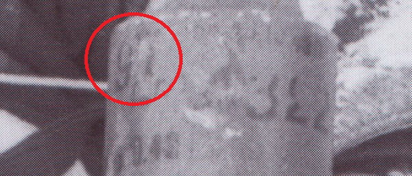 The 8,8 cm R PzB Gr. 4992  This model was an improvement
over the 8,8 cm R Pz B Gr 4322. It
utilized the same warhead, the same fuze, the same igniter and the same
rocket
motor as the 8,8 cm R Pz B Gr 4322 Arkt. 1944/45 version, but it had an
improved tail drum that incorporated a contact ring. This would enable
the
loader to skip the manual step of plugging the rocket igniter to the
connector
box during loading. This could only be used on the R PzB 54/1 that was
rebuilt
with a new model of connector box. Read more about this on the page
concerning
the R PzB 54/1 Markings,
paint and manufacturers 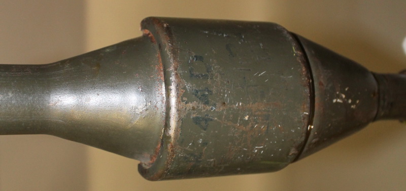 The Paintwork on the 8,8 cm R Pz B Gr 4322 was
regulated in the
Heerestechnische Verordnungsblatt 1. September 1944: "Geschoßkopf
feldgrau, Brennkammer phosphatiert, Leitwerk Schwarz." (Warhead
Fieldgray,
Motor phospated, Tail drum black).   The rocket motor had the model painted on in
white paint; “Arkt.” or “Arkt.
44/45”. In addition the maker and year could be found in white
paint. An Arkt. 44/45 motor manufactured by fsv in 4 (late 1944)
Packing material for ammunition 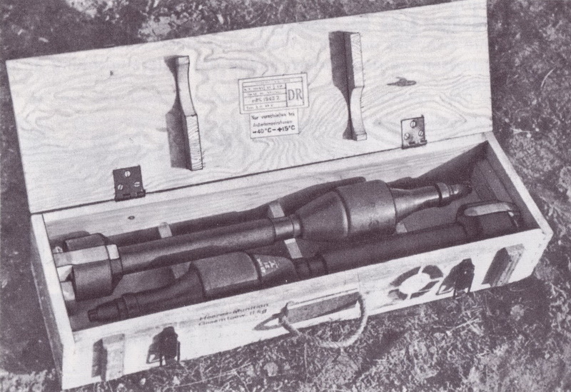 The 8,8 cm R Pz B ammunition came in pairs in a wooden box with the designation “R-Munitionskasten 4322”. The box had a plywood lid, dovetailed corners and a handle that consisted of a rope. Metal was only used on hinges, clasps, nails and screws. Internally a set of 5 spacers kept the grenades firmly in place to avoid damage during transport. The box would weigh 4,4 kg empty and 11 kg with complete contents. The external finish came in a wide variety of unpainted, Dunkelgelb, light grey, charcoal black or Dunkelgrau, with a light finish being the norm. 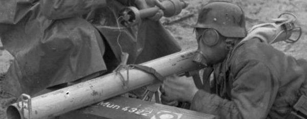 A rainy day on the range. Note the Dunkelgrau ammunition box with white stenciled text. The markings found on the box always followed the same pattern. Some markings were standardized on all boxes and others would depend on the ammunition it contained. 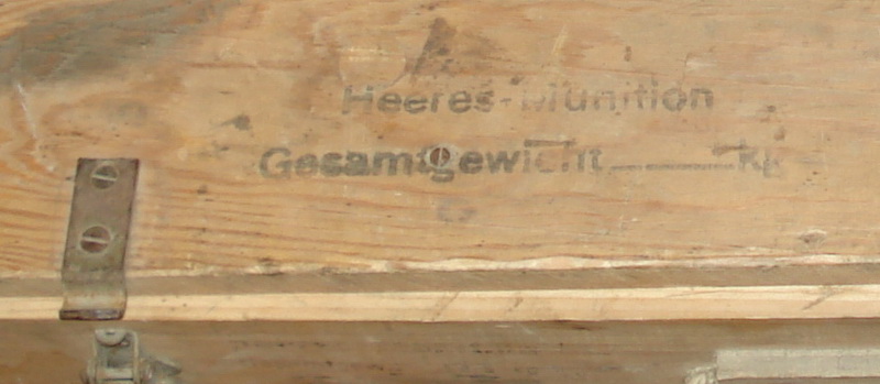 “Heeres-munition Gesamtgewicht 11 kg” (Army ammunition, combined weight 11 kg) would be stamped in two lines on the left front and on the lower left of the lid. Sometimes the weight was a part of the stamp, and sometimes it had to be filled in manually like this one.  “R Mun
4322” was painted on in a large font centred on the lid. This
abbreviation stood for “Raket
Munitionkasten
4322” (Rocket ammunition As discussed above, the rocket motor came in 3
different varieties. In addition a dummy grenade with a live rocket was
also supplied for target practice. To ensure that the operator knew
what type of ammunition or what type of rocket motor he would be
shooting, each box was clearly marked with a symbol or text. The Technische Heeresmitteilungen from 01.
September 1944 and 15. January 1945 gave a detailed description of the
size, form and position of each symbol. These were also listed in the H.Dv 1864/6 from 01.12.1944.
Examples of all the variations
described above. Note that the Arkt 44/45 box is
a recycled Wintermunition 1943/44 box with the
ring covered by paint.
The dummy grenade with live rocket motor is not
described in regards to marking practice of the ammunition box, but a
surviving specimen shows that it was simply marked “Bl” (for Blind) in black instead
of the other symbols. The “R Mun
4322” was kept, even though the box contained two 4320 grenades! Assorted paper labels were glued on the box
according to the contents of the box. The same labels would appear on
the outside of the box as well as on the inside of the lid. The main
label described the contents in detail as follows:
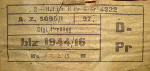 1. 2 -- 8,8 cm R
Pz B Gr 4322
2 pieces -- Designated abbreviation for
the grenade When
comparing these labels with the tabular above it is obvious that there
must have been differences between the manufacturing batches of the
grenades as well, as some of these temperature ranges differs from the
listed variations. The top of this section show a Dias of a full, open
box. The label is hard to read, but the temperature range is easy to
see; -40 to +15. Yet another variation!
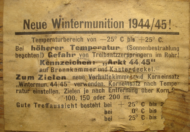
The inside of the Wintermunition 1944/45 box had a special label that stressed that this was a new ammunition and that it had to be used with the new sights. See the page about the sights for more details.
Fragment of a similar label from another box , but clearly printed by another manufacturer. The
cardboard wrapping A new type of packing material for the
Panzerschreck rocket was announced in the manual H.Dv 1864/6 published on
01.12.1944. It states that “A cardboard tube for one grenade that can
be carried on the back will be issued in the future instead of the
ammunition box”. 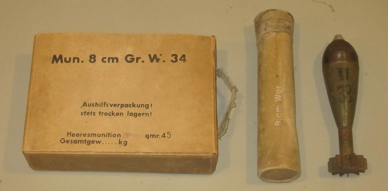 The picture above shows a (very) late war cardboard wrapping box for 8 cm Mortar ammunition. The 3-round box for factory-frontline transport was normally made of wood. It is not unlikely that the production of a similar packing material set was made for the 8,8 cm R PzB Gr. 4322. Makers of ammunition and ammunition parts The main manufacturers of ammunition for the Panzerschreck appear to be WASAG and Eibia. These are the only codes that appear on the labels inside the packing crates. But the components for the grenade were manufactured by a large number of subcontractors.  This "Arkt" grenade can serve as an example. Fuze made by gcy, warhead body made by fcc, rocket motor made by fsv, rocket fuel unknown, igniter made by am, booster unknown and finally filled by rdf. The following list are codes and manufacturers associated with the manufacture of the 8,8 cm R PzB Gr. 4322. There will be a whole lot more added as I find them.
The following pictures are samples of box labels from different lots. 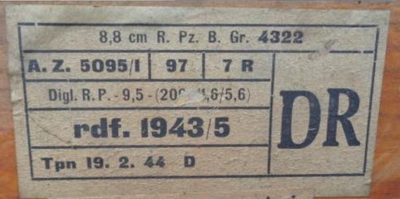 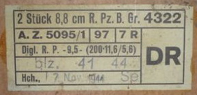 The last two labels differs from the ones above, as they have both printed "2 Stück" (2 pieces) on the first line. The explanation to this can be found in the lower left corner. While all the rockets above were shipped (and possibly packed) by Heeres Munitionsanstalt Töpchin (Tpn), the last two boxes were shipped from Luftmunitionsanstalt (L.Ma.) Hohenleipisch (Hch). This practice changes with the new rocket motor. 
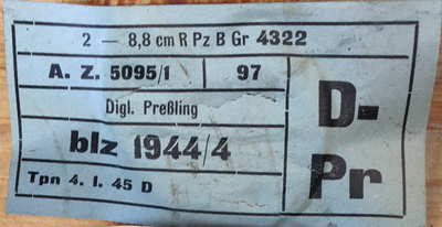 The first label above comes from a Arkt 44/45 box. It simply states "2" instead of "2 Stück". It was shipped from (and possibly packed) by Heeres Munitionsanstalt Walsrode bei Hannover (We). The second picture show that Töpchin also states "2" on the label for the Arkt 44/45 rockets. 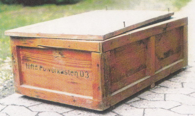 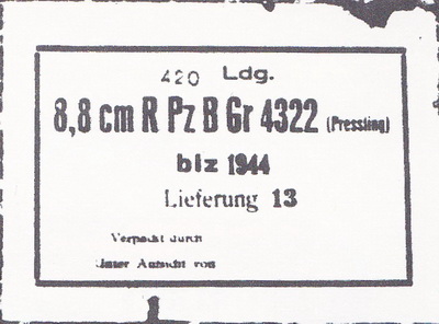 The box above is a standard "Luftdichter Pulverkasten 03" (Airtight Powder box 03), and it was used for transport of components between the factories making parts for the rocket. This one contained 420 rocket fuel assemblies for the Wintermunition 1944/45 (Pressling was the compact "wheel" type). For details about transportation of the ammunition see my new article about the transport of the Panzerschreck 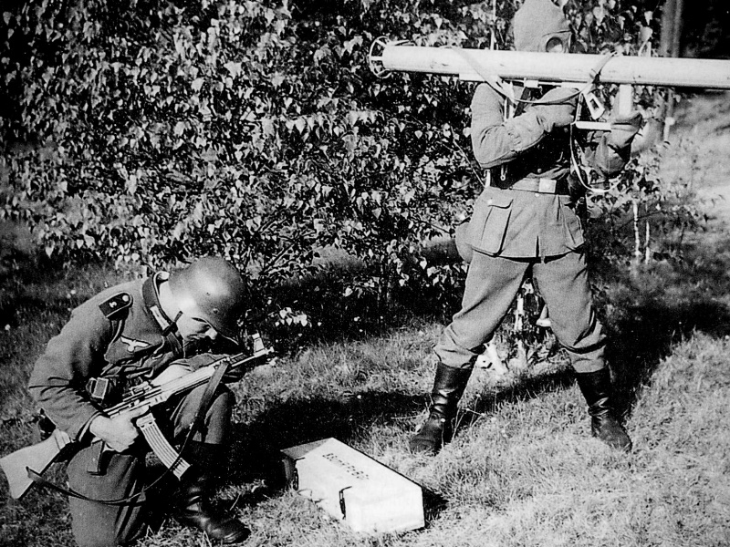 A picture from testing and development, mid-1943. The kneeling loader carries a MP43/1. The text on the ammuniton box is "8,8 cm R Pz B Gr". Most probably a prototype, as the text is only known from this box/picture. NEW ADDITION 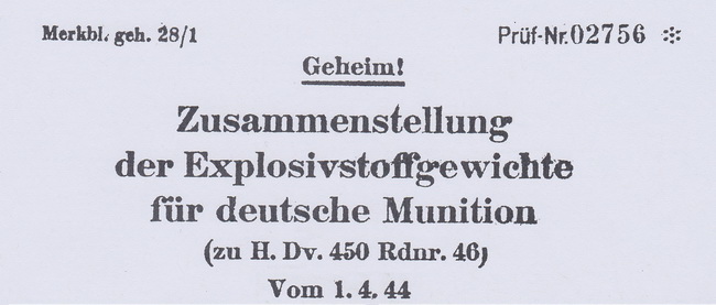 The above pictured Merkblatt was a list that was issued to all (resuply) units resposible for handling and storing ammunition. The list was used to determine the total amount (weight) of explosives present in any given number of ordnance items. The total amount of explosives on a train, in a bunker or on a truck could then be calculated to avoid excessive damage if things should go wrong... And the actual weight of the ammunition would be of no use, as the weight of the casings, packing & transport material etc would give misleading figures. 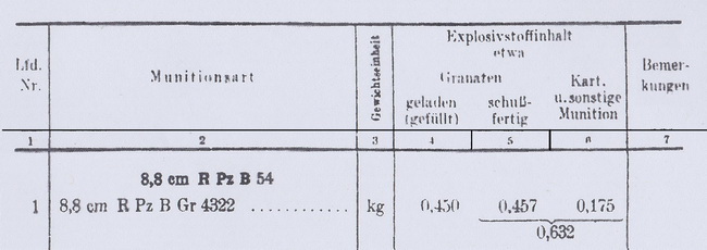 The 8,8 cm R Pz B Gr. 4322 was listed with the following details. The rocket head was filled with 0.450 kg of explosives, and the fuse with booster obviously contained 7 grams of explosives, as the weight of the ready round was listed as 457 grams. The "explosive" weight of the rocket motor with the black powder charge was listed as 175 grams. The total weight of explosives for one rocket was 0,632 kg. Alternative use 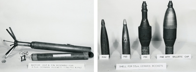 The 5,5 cm R4M rocket was developed for use by the new jet fighters, and was ready for serial production in September 1944. It was fired in pairs, and each fighter would carry 24 rockets. The R4M warhead was HE (High Explosive), and out of a salvo of 24 rockets the scientists anticipated two hits on a bomber formation. The 5,5cm PB3 warhead incorporated the shaped charge principle, and was intended for use against tanks. The effect of the PB3 warhead was probably not satisfactory, as the warhead from a standard 8,8 cm R Pz B Gr 4322 was mounted on the same rocket motor and given the designation PB2. A ballistic cap was also manufactured for the PB2 warhead to give it improved "flying" qualities. The PB2 used the same fuse as the 8,8 cm R Pz B Gr 4322. The warheads were clearly lifted right out of the standard ammunition production, as they even carry the standard WaA marking in white ink. |
| Home | For sale | Site map | Contact information | Guest book | The Panzerschreck Lounge |