
| Home | For sale | Site map | Contact information | Guest book | Leuchtpistole menu |
 Assembly & disassembly of Die
Leuchtpistole Assembly & disassembly of Die
Leuchtpistole |
|---|
|
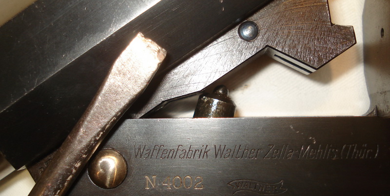
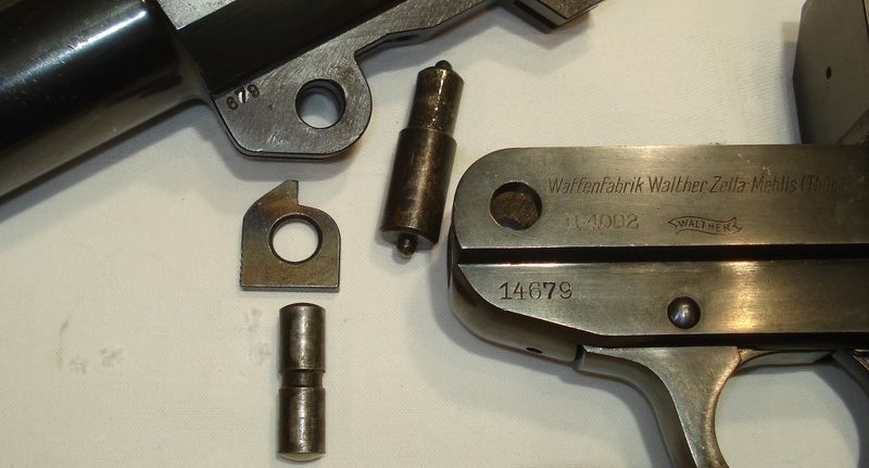
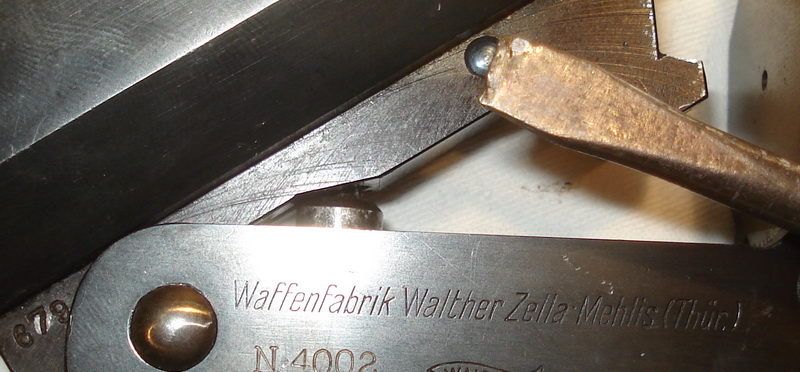
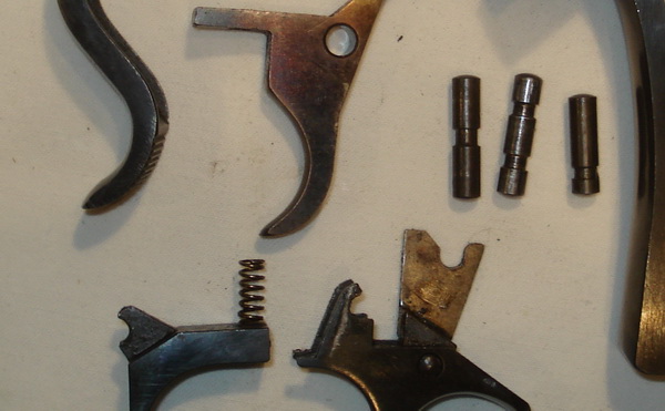
"Some assembly required......" 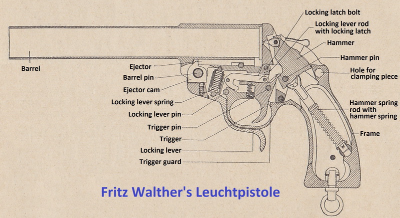 The flare gun was not to be disassembled by the user. It was normally cleaned and maintained in the assembled state. Disassembly was only done by a Waffenmeister or a higher echelon workshop. Dienstvorschrift 884 from 1929 «Richtlinien für das Zerlegen und Zusammensetzen der Leuchtpistole» (Guidelines for disassembly and assembly of the flare gun) begins with the following text: (Only applicable for weapon workshops.) At the same time, the sales prospect for the civilian market contains an illustrated manual for disassembly and assembly to be performed by the potential customer. The following text from the manual is also well worth noting: "Jede Anwendung von Gewalt muß vermieden werden " (All use of force must be avoided). With experience and training, the flare gun construction is easy to master, but unnecessary disassembly will increase the chance of breakages. There is also an array of small parts that can be lost during disassembly. The following description of the disassembly and assembly procedure is based on personal experience, and will be useful to better understand how the flare gun works. If you are planning to disassemble the flare gun yourself it might be wise to take it step by step, and to reverse the procedure for each step. Once a part is out, assemble it again before you move on to the next step. This is the “easy” way to avoid ending up with a bunch of parts and even more questions. The first thing to do, as always when handling a gun, is to check that the gun is empty. This is easily done by pressing the locking lever forward, freeing the barrel locking lug and allowing the barrel to revolve round the barrel pin, exposing the chamber. The next step is to visually check the flare gun. It is important that all pins are present and correct. If any of the pins are broken, further disassembly of the flare gun is not recommended unless spare parts can be sourced. Broken pins can usually be identified through a visual inspection. When a pin breaks, the short part will normally be lost, while the longer part stays locked in position and sometimes allows the flare gun to continue to function. The part that falls off will leave a hole in the side of the frame. Although the flare gun might continue to work with a broken pin, assembling it again if taken apart might prove very difficult unless a spare part can be sourced. The pin that has the highest rate of breaking is the trigger pin (the one with two grooves). The disassembly procedure comprises three main groups of parts; the barrel, the hammer spring and the trigger- / release lever mechanism. Normal disassembly is done without the use of any special tools, with the exception of the grip plate screw that requires a standard screwdriver. Parts that require the use of special tools are normally not dismantled. This includes the ejector, the locking lever/rod/latch assembly, the hammer spring guide assembly, the bolt and spring for the ejector cam, the locking bolt for the locking latch and the trigger guard with the guide for the hammer pin. These components are normally left assembled, and replaced as complete units. Further details on this will be available on the Accessories pages, under the chapter about the spare parts box. The barrel
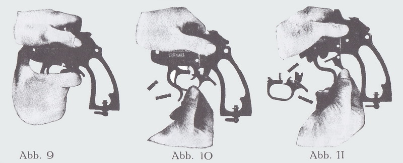
Use a simple tool, such as a screwdriver or a knife edge, and tilt the top of the release spring sleeve or the release spring guide (mid to late-war production) backwards. This will release the spring and remove the pressure from the barrel. The barrel will now swing freely around the axis of the barrel pin. By applying thumb-pressure on the pin, while at the same time revolving the barrel round the pin and opening and closing the barrel, the pin will work its way out.
When the barrel pin is completely removed, the barrel will separate from the frame, and the locking lever spring unit and the ejector cam can be removed. Further disassembly of the barrel is not recommended.
The bolt and spring for the ejector cam is situated in the frame, just below the hole for the barrel pin. This unit rests in a channel that has been drilled all the way through the frame. The bolt and spring is normally secured through friction, but sometimes this tiny bolt is loose. It will work all the same, but can easily be lost during disassembly, so precautions to avoid loss should be taken.
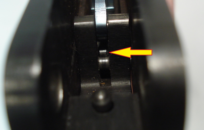
When assembling the barrel it is essential to place the locking lever spring inside the frame first. The early to mid-war version of the spring is housed inside two sleeves. The thick sleeve is situated in the bottom and the narrow sleeve is on top. The mid-war to late-war spring has a guiding piece on the top of the spring. The spring should remain “loose” for the time being, pointing upwards and backwards. The ejector cam is placed in its slot in the barrel, with its hole flush with the hole of the barrel pin. The serrated side should point forwards, the small “tooth” pointing upwards with the vertical side pointing backwards (see picture further up). The ejector cam should be angled so that the lower surface corresponds with the frame. The barrel and frame is then held together so that the hole for the barrel pin is flush, allowing the pin to be pressed in with the thumb. To facilitate the process, it may be necessary to move the barrel and the frame in the same opening and closing motion that was used during disassembly.
With the barrel fully tilted forward the upper part of the locking lever spring is pushed forward until it snaps into position. The top of the locking lever spring now rests in the upper bearing for the locking lever spring in the barrel rail. The correct functioning can now be asserted by opening and closing the barrel. If the locking lever spring sleeves have been inserted upside-down it will not be possible to close the barrel. Hammer spring
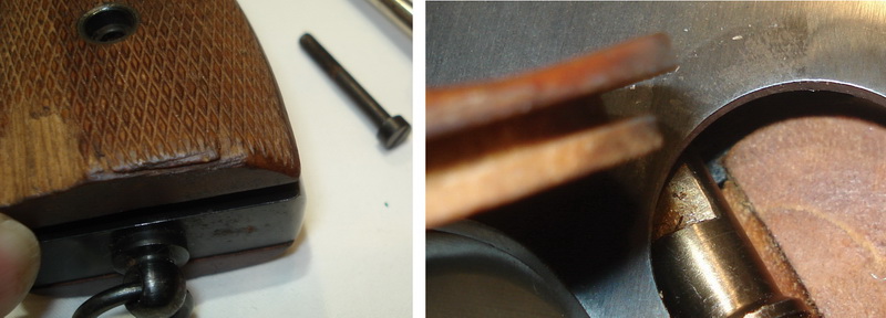
To remove them they have to be pulled out in the bottom so far that the inner lining clears the frame and then pulled downwards. If this is not possible, they can be moved gently back and forth until they lose their grip (pun intended!) and can be pulled down. If they are pulled outwards it will cause the inside lip to break. If the flare gun is equipped with the third model of grip plates, the screw can be unscrewed and the plates lifted straight off. The third model can be identified by a much more narrow design with a smooth surface around the screw hole in the Bakelite.
When the grip plates have been removed, the hammer spring guide (on the end of the hammer spring rod) can be squeezed out sideways from its resting position. The hammer will then lose the spring tension, but will not be removable as the hammer pin is still held in position by the hammer pin guide.
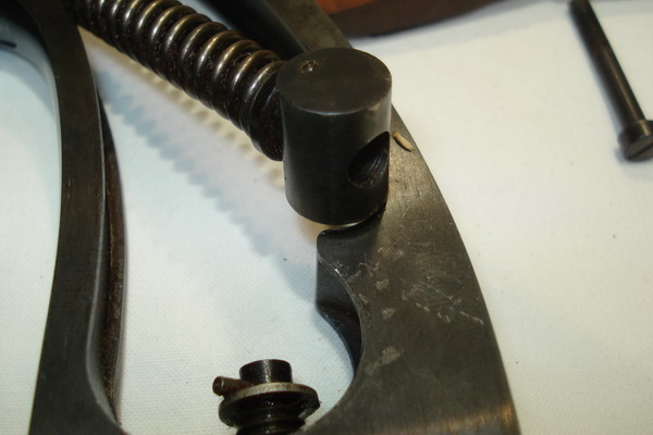
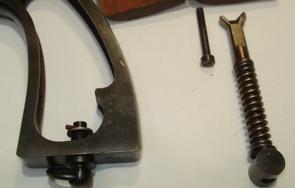
The hammer spring rod has a
fork on the top, where the longest fork leg should point backwards.
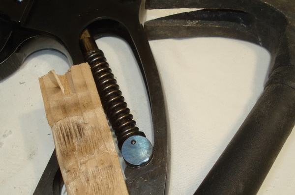
Depending on the tolerance limits and wear, it will be possible to push the hammer spring guide into position by hand. Place the flare gun on a soft layer (towel) to avoid damage, but with a firm surface. Press the hammer spring guide upwards in the longitudinal direction of the hammer spring rod using a piece of wood, while pressing it slightly sideways. When the hammer spring is sufficiently compressed, it will snap into the resting position. If the spring is stubborn (hard), you can use a hammer on the piece of wood and give it a short and hard stroke so that the spring is compressed and the guide is slid sideways in one movement. Getting the hammer spring back in position is the most difficult operation during the assembly of the flare gun. The grip plates are pressed in on the top and slid up so that the lip locks inside the frame. When the plates are slid far enough up they can be pressed in at the bottom and the screw mounted again.
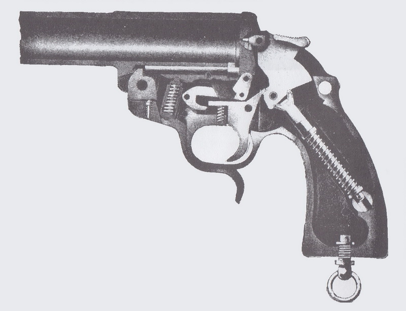
Excerpt from Waffenfabrik Walther's sales brochure from the early 1930s
Trigger and locking lever mechanism
The start position for this description is with the barrel and the hammer spring disassembled. The previously mentioned "multi-functional" trigger guard is the lock which holds both mechanisms in place.
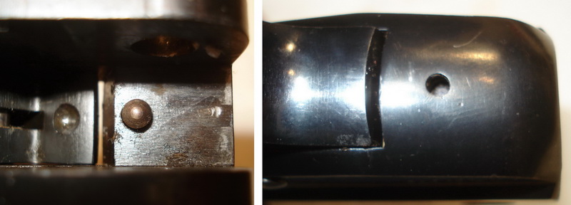
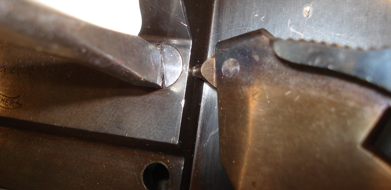
Now, the three pins can be pushed out sideways using the grip plate screw as a tool, and the trigger and hammer can be removed. The locking lever will still be linked to the locking lever rod and the locking lever latch, but without removing the pin for the locking lever, it will be difficult to remove the trigger guard. The last operation is to remove the locking latch bolt. This sits just below the bottom of the breach face and looks like a screw. It has a transverse locking bolt that rests in a channel in the frame that points straight backwards.
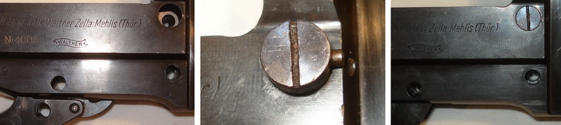
To disengage this, push the locking bolt forward by pressing the tip of the firing pin into to channel and at the same time rotate the “screw-head” slightly. The transverse locking bolt is now freed from the locking position, and the locking latch bolt can be pushed out of the frame from the right to the left. The small transverse locking bolt must be attached to the locking latch bolt with a punch mark. If this is not in place, it will be pushed out sideways, so keep control of this when the bolt is removed.
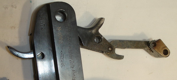
The locking lever, locking lever rod and locking latch form a unit. This is held together by pins and should not be dismantled further. To get it out of the frame, it is pulled out through the opening at the top of the frame.
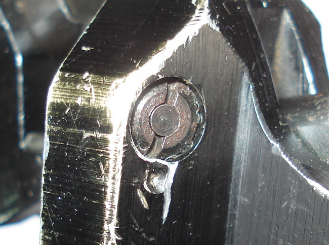
The chamber indicator (if installed) can be unscrewed with a special screwdriver, but should normally be left alone. (Note the punch mark, securing the screw). The flare gun is now considered disassembled and further disassembly of the parts is not recommended. --------------------------------------------------------------------------------------------------------------- At this point the manual has an easy solution; it simply
states “assembly takes place in reverse order”!
Locking lever pin - center groove
Start with the locking latch and the locking latch
bolt. Remember to turn the "screw head" until it locks.
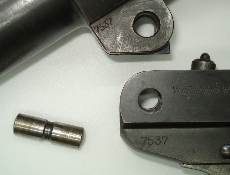
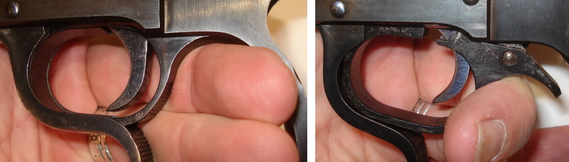
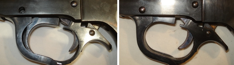
The next step is to install the trigger. The pin for the trigger has two slots, as there are two arms on the top of the trigger guard that holds it in place. These should be on each side of the trigger, so it is important to try to center the trigger on the pin.
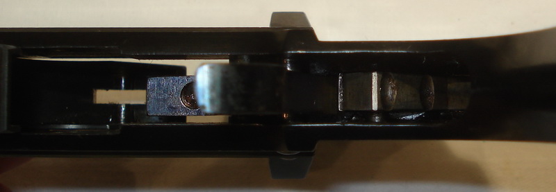
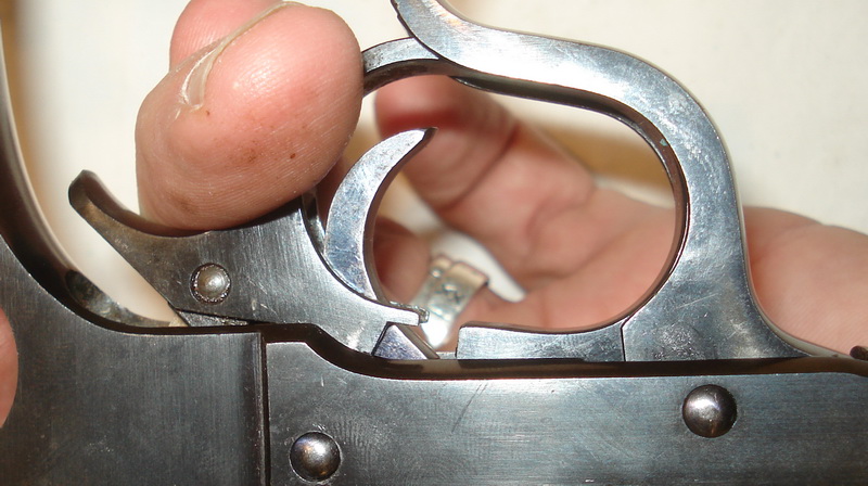
The trigger guard is then placed loosely in position before the locking lever is mounted with the locking lever pin. This last pin has one centered groove which corresponds to the crescent-shaped arm on the front of the trigger guard. To mount the trigger guard, insert the crescent-shaped arm in front in the groove of the locking lever pin.
This can be verified by looking at the pin from the top of the frame. It is now easier to work if the frame is turned upside down. Once it is confirmed that the crescent-shaped arm sits in the groove of the pin, simply push the trigger guard (forward) and move it into the frame and release. Note that the pins must be roughly correctly positioned for the crescent-shaped recesses to hit the grooves on the pins. This can be verified by visually checking that the pin heads are flush with the outer walls of the frame.
The
trigger and release mechanism are thus assembled again, and
the hammer spring and barrel can be assembled. To make sure everything
has been done correctly, a visual inspection of the exterior should be
made to ensure that the pins are placed correctly and that the trigger
guard covers the hole in the frame. Assemble the hammer spring, grip
plates and barrel as previously discussed. 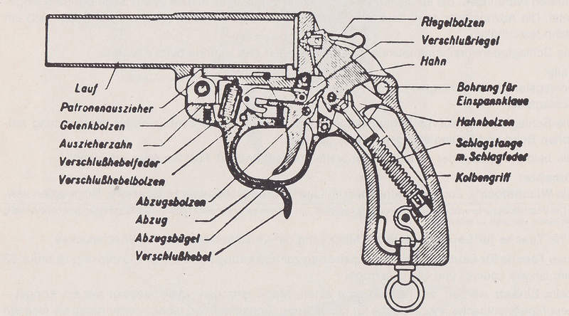 |
| Home | For sale | Site map | Contact information | Guest book | Leuchtpistole menu |