
| Home | For sale | Site map | Contact information | Guest book | The Panzerschreck Lounge |
 Panzerschreck
- The firing system Panzerschreck
- The firing system
|
|---|
The spark that lights the fire The Puppchen was already under development when the US M1 Bazooka was captured in Tunisia. Initially, the German engineers were interested in a mechanical ignition system, involving a firing pin and a good old percussion cap. This was used on the 8,8cm Raketen Panzer Granat 4312 for the Puppchen, which fired from a closed tube with a breech-block. The captured US M1 Bazooka was fired with a flashlight battery producing the current needed to ignite the rocket motor, a system that was deemed ineffective by the Germans, mostly due to the severe problems this would create in a cold environment like the Eastern Front. But as late as 23 September 1943 they still played with the idea of using a battery, and "Testing with a battery that would work in a cold environment" was given as one of the excuses why the first batch of Panzerschrecks wasn't ready for the frontline. When the first attempts of using a mechanical principle with a percussion ignition failed, they came up with a new idea. The result was a 50/50 solution. A mechanical spring pressured trigger system releases a driving rod. This will in turn hit a "Stoßgenerator" (a punch generator) that will produce the current necessary to ignite the rocket motor. This does away with the need for a battery and is reusable over and over again. The mechanical firing system The firing mechanism had three stages or phases.
Pressing the trigger will release the rod which will strike against the generator producing a electrical current and the mechanism will return to stage 1.
The electric circuit
There is a closed electric circuit that runs from the generator (Stoßgenerator) to the outlet box (Steckerbuchse) mounted at the rear end of the tube.
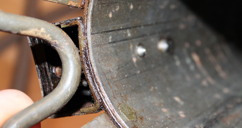
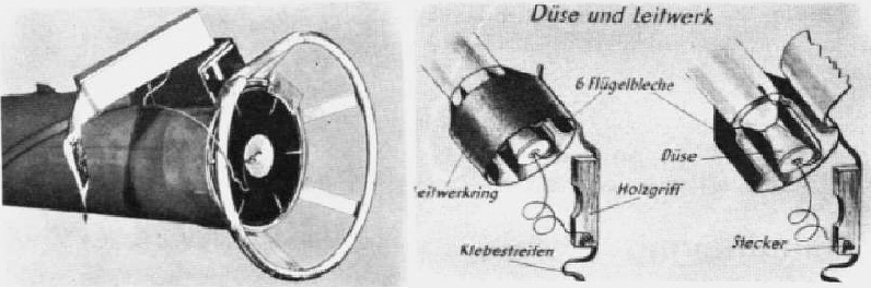
The Stoßgenerator works on a simple principle. The visible metal disc is held by a rubber disc and will not move much, but the impact shock created by the rod will travel from the metal disc to the movable iron core, sending this one to the rear. On its rearward movement it passes through a copper wire spool and a circular magnet and induces a current. A spring at the rear pushes the iron core back again so that it rests against the metal disc again. Due to this construction all the moveable parts are held inside the closed casing. The rocket that is loaded into the tube from the rear has a wire protruding at the end which is terminated in a wooden contact holder with a plug. This plug is inserted into the outlet box. The electric current produced by the generator will travel through the wire, via the outlet box and into the rocket engine, igniting this. The return current will travel from the engine through a second wire that is soldered to the rocket body inside the tail fin ring and back into the outlet box through a spring pressured pointed pin that grounds the rocket fin ring once the rocket is inserted.
With the introduction of the RPzB 54/1 a whole new and simplified connection system was adapted, together with new ammunition. These improvements will be discussed in the page concerning theRPzB 54/1. The firing system in (extreme) detail The parts for the firing system were mounted after the tube had been painted. The finish appears to be a thin zinc coating.
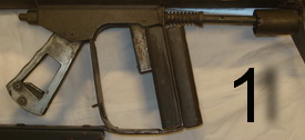
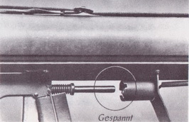
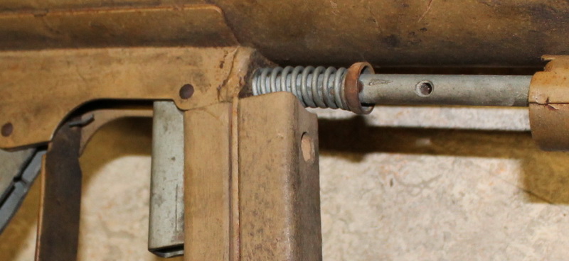
The spring that drives the firing rod can be found just above and to the rear of the trigger. It is held in place by a cross pin and a cup washer. When the cup washer is under pressure from the spring the pin will be held in place. The firing rod has a second hole with no apparant function. Most likely this hole was used for a special tool when the cross pin/cup washer/driving spring was installed. The firing rod has a
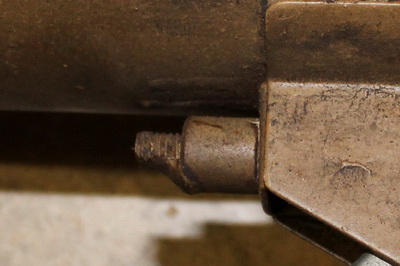
threaded portion to the front,
where a nut is screwed on and welded in place. This part was obviously
not meant to be adjustable. The nut comes in two varieties, one which
is smooth and one with the standard 6 sides.
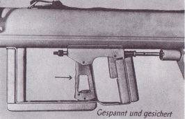
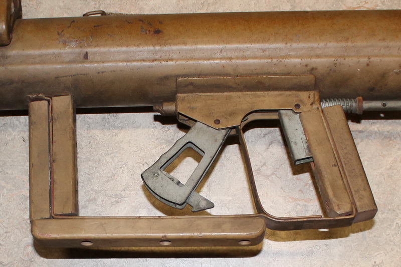
Both the trigger and the cocking handle had their own return springs. There was also a spring built into the cocking handle for the safety catch.
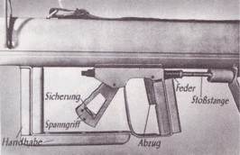
The details and measurements of the separate parts can be studied in the technical drawings by William Bogdan in the pictures above. The improved safety catchThe
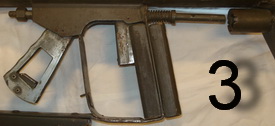
safety catch on the standard RPzB54 consisted of a small spring
pressured catch that was built into the cocking handle. This would in
turn hook up with a small eyelet that was welded to the grip frame. The
safety & eyelet was fragile and it was clumsy to operate, as
the firer would
have to stick his thumb inside the cocking handle to disengage it.
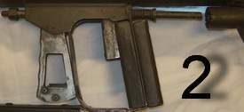
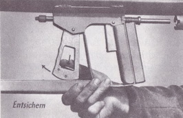
 The
improved safety catch had a simpler design. Instead of the welded
eyelet on the grip frame a simple slot was made. The safety catch was
made
longer and had a hook that engaged directly in the grip frame. This
made
it much easier to operate, as the firer could just press the hook
upwards to disengage it without letting go of the trigger grip.
 Production was also slightly simplified, as this configuration only needed one rivet instead of the normal two. The first safe indicator of its introduction is the "Von der Front für die Front" about the DZG, dated 10 October 1944. 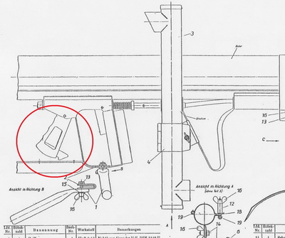 This drawing shows the second type of safety and proves that it was in production at this time. It is still unclear when it was first introduced. The introduction of the new safety and the improved front sight frame did not happen at the same time. It
only appears on 50% of the RPzB 54/1 made available to the troops from
January 1945, the rest of them have the old safety. The explanation for
this is simple and will be revealed in the RPzB 54/1 section. The new
type
safety is not a result of an upgrade, as that would have left a
rivet hole.
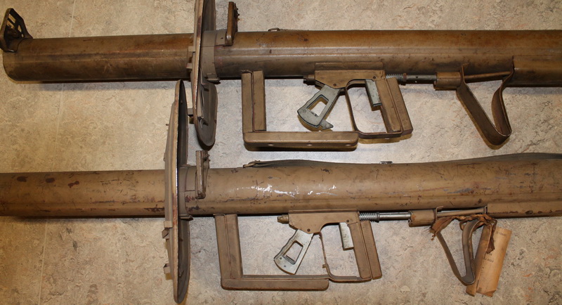 Both weapons above are kxs made. Both have the Model III front sight from mid-1944. And they have different safeties. We can safely assume that the upper one was a later manufacture. 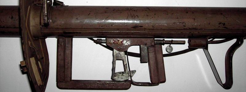 A RPzB 54/1 in a German Museum 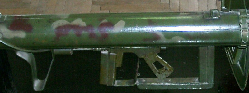 RPzB 54/1 in a Russian museum |
| Home | For sale | Site map | Contact information | Guest book | The Panzerschreck Lounge |