

| Home | For sale | Site map | Contact information | Guest book | The Panzerschreck Lounge |
 The
Panzerschreck user guide The
Panzerschreck user guide
|
|---|
|
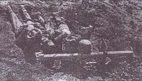
Practical use For
all practical purposes the Panzerschreck is just a piece of metal
tubing with an outdated electrical current producing system. The
"dangerous part" of it is the rocket that is long since gone. But it
is still considered a weapon by most governments today, even
though ammunition is unavailable. I
have never heard about a "live" Panzerschreck round that has been fired
in modern times, but to satisfy my American readers:
Disclaimer! None of the text on these pages must be considered as
guidelines for actual use, and I will not be held responsible for any
damage that might occur from use of an actual Panzerschreck. These
pages
are a theoretical study only!
To be able to describe how the actual weapon was used, combined with the drills conducted by the crew, the best source is the actual user manual; the D 1864/1. Since this is written in German and most of my readers are "less than fluent" readers of German (including myself) I have chosen to translate it to English. I have kept the layout and original pictures from the manual, but left out the index and non-interesting bits. The complete original manual is downloadable here. After the English manual below you will find a translated version of the Panzerbeschuß tafel nr 25, which is also an important part of the practical use. The Merkblatt 77/2 has the instructions for educational and tactical use of the Ofenrohr. This has not been translated yet, so only the original version is available. A US contemporary study of the tactics applied by Panzerschreck crews can be studied at Lonesentry.com. Time to see what the manual dictates then! User manual for the Panzerschreck 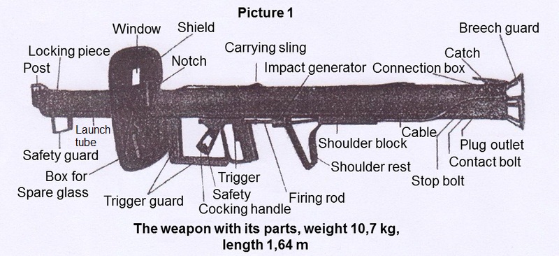 A.
Weapon 1.
What
is the Panzerschreck? 2.
The
weapon and its parts (Picture
1) 3.
Weapon
care B.
Ammunition 4.
What
is the 8,8 cm R PzBGr 4322? 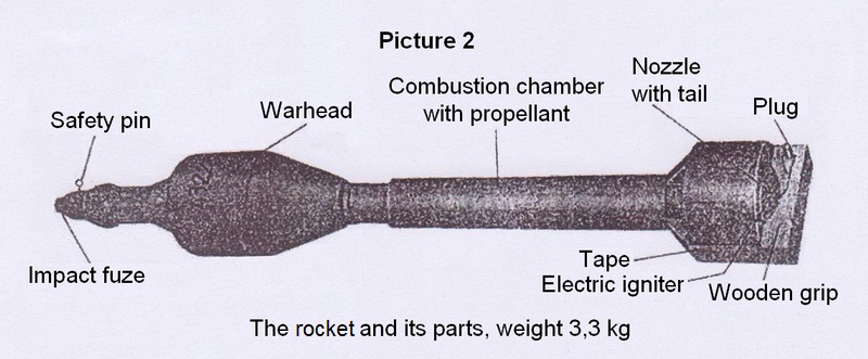 5.
The
rocket and its parts (see
picture 2). 6.
Handling
of the ammunition 7.
Care
of the impact fuze 8.
Further
ammunition types: C. Use
9.
Preparations
before use Picture 3
Picture 4
10.
Loading a)
Gunner: b) Loader: 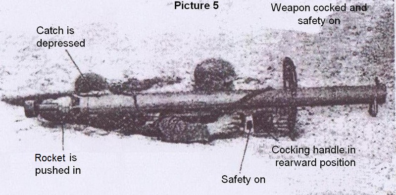 Change the grip, grasp the
nozzle (see picture 6) and push the rocket lightly
into the launch tube until it stops against the stop bolt. Picture 6
 Release the catch and pull the rocket rearwards until it touches the catch (see picture 7 and 8 for positioning of the tail-section).  Plug the contact into the
contact box, move hands away from the rear end of the launch tube. Keep away from the rear end of the weapon; otherwise you will be caught by the jet fire!  Hands away when the weapon is
loaded and the plug has been inserted! Turn face
away from the launch tube when the weapon is fired! 11.
Firing a) Release the safety catch:  b)
Aim
over the notch and post (see
picture 10). 
c) Aiming points: 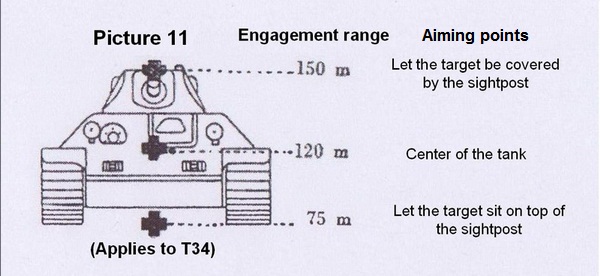 With engagement ranges less
than 75m the aiming point must again be
higher. When
shooting uphill or downhill:
aim lower; for example if the difference in ground height is 300
and
the engagement range is 120 meters let the target sit on top of the
post. 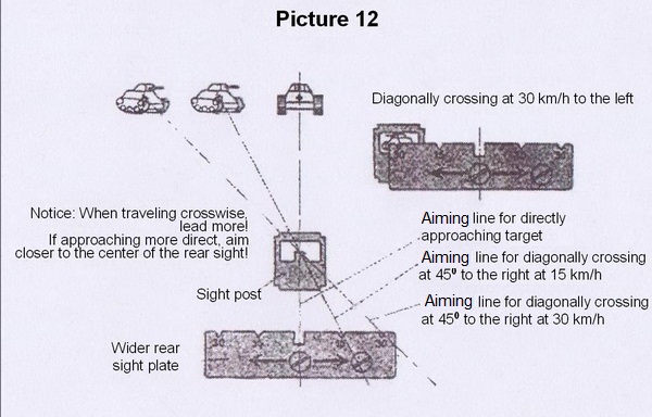 d) Lead allowance: e)
Range
finder: Picture 13
 f)
Firing: g)
When
changing position with a loaded
weapon make sure that the safety is on. 12.
Process
during firing: 13.
Failure
to ignite: 14.
Unloading: 15.
Duds
and unserviceable rockets must
be blown up by technical personnel. 16. Danger! A jet fire will be emitted from the rear end of the launch tube. The ignition device will fly 30 m to the rear. Loader: Pay attention during change of target and position. Keep away from the end of the launch tube. Keep flammable objects away. Place ammunition to the side.
Annex 1
Instructions
for the mounting of shield, safety guard and adjustable sight with
cover
plate on earlier versions of the weapon 17.
Shield a. Installation:
Install the shield in
front of the rear sight with the box closer in such a way that the
shield is
held tight and the gunner can aim withouth any obstructions through the
window.
The shield should
always be mounted on
the weapon. Only to be removed during transport as goods. b.
Installing
and changing
the
glass: The glass in the window
and the
spares carried in the container on the shield should all be framed on
both
sides according to picture 14 with ammunition-tape, insulating tape or
similar
product prior to shooting. One
piece of
glass should be installed in the window, the rest in the container. 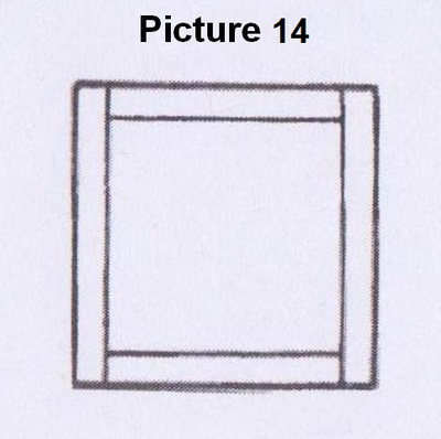
Glass
that hasn’t been taped will shatter.
Replace shattered or cloudy glass with new ones. 18.
Safety
guard 19.
Adjustable
front sight 20.
Cover
plate 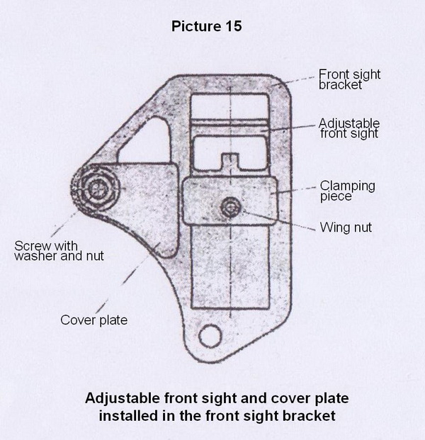 Annex 2 Checking
and adjusting the sight line Check
and adjust the sight line whenever the opportunity arises, if possible
by technical
personnel. 21.
Draw up a target board according to
picture 16. 22.
Place the target board upright at a
distance of 10 m. 23.
Use a triangular file and cut 4
grooves in each end of the launch tube at a 900
angle
opposing each other
(grooves should be 1mm deep). 24.
Place the launch tube axis on the aiming
point S. 25.
Adjust the front sight in height,
and for newer weapons the rear sight sideways, so that the sight line
is
aligned when the top of the front and rear sight aims at the lower edge
of the
upper aiming point V (for winter ammunition at +200
C). Place the upper
alignment mark at the sight
bracket in the same height as the mark on the adjustable front sight
(according
to picture 10). Place
the lower mark
(for winter ammunition at -250 C) the same way. 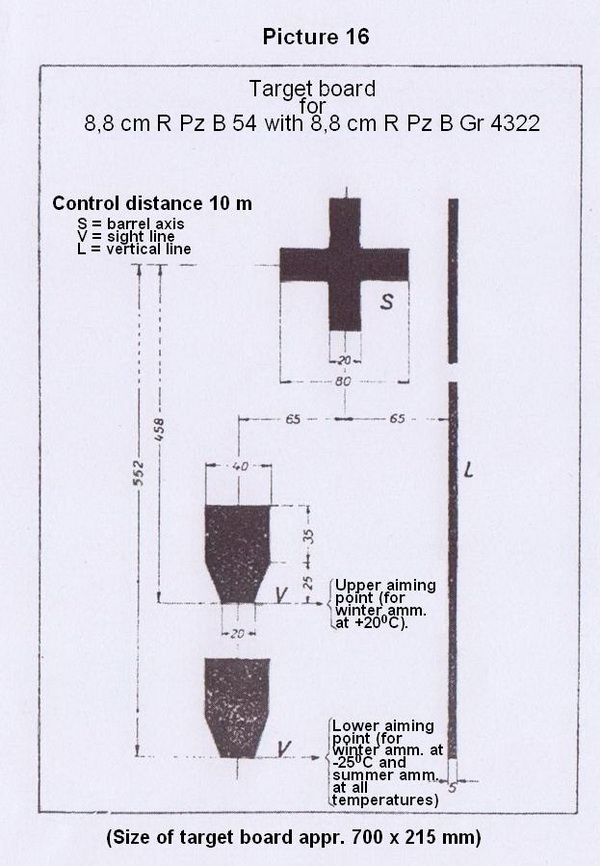 Improvements
suggested by the units 26.
Make a hand
guard according to
picture 17 from sheet metal and install it to the upper part of the
shield with
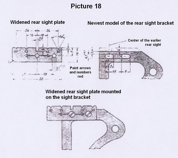
a screw and nut, friction will hold the lower part. 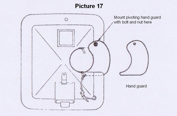 27.
Make
and install a widened rear
sight plate. Make
a widened rear sight
plate according to picture 18 from 1,5 mm thick sheet metal and reduce
the
height of the rear sight bracket by 4 mm. Replace the old sight plate
with a
widened sight plate in the middle of the bracket with nuts and screws
(for
practical use see Nr. 11d.)
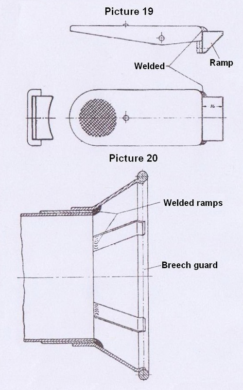
28. To ease the loading of the rocket a ramp should be added to the catch (picture 19) and separate ramps welded to the struts of the breech guard (picture 20).
Anti-Tank
Target board Nr.
25 8,8 cm R
Pz B 54 with 8,8 cm R Pz B Gr 4322 Effect
Information about the weapon and its use, aiming points, leading distance and so on can be found in D 1864/1. Combat
range up
to 150 m
Guidelines
for fighting enemy tanks 1.
Keep
calm and be cold-blooded! Let
the tank come close. Shoot at the closest possible range. 2.
Camouflage! Use
every opportunity to
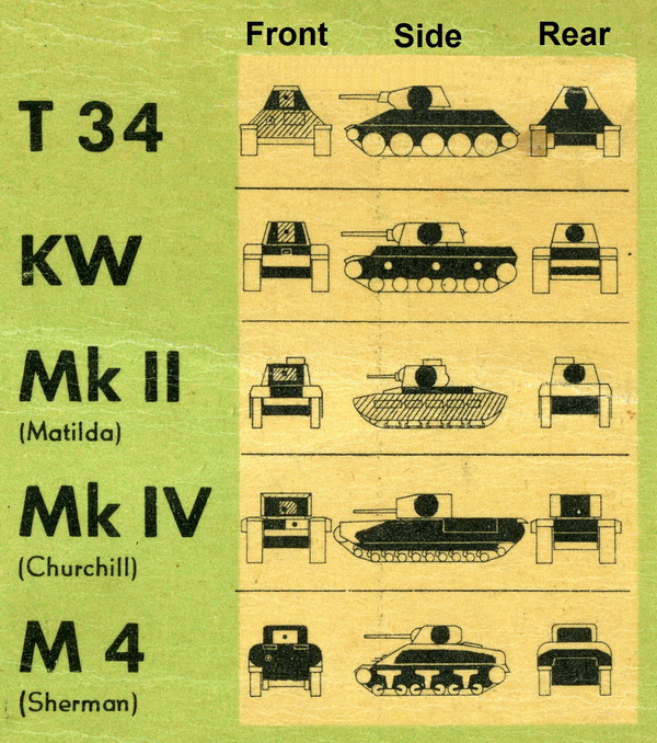
camouflage. Whenever possible, fight enemy tanks 3.
Judge
the distance meticulously! Aim
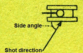
carefully! 4. Obtain the best possible
impact angle! Best effect is obtained when the front or
side is fully
5.
Observe
the effect of the rocket!
All hits haven’t got a devastating effect. 6.
Take
care of the weapon and
ammunition. Correct care and cleaning will reduce the
The
8,8 cm R Pz B Gr
4322 will detonate at impact with the armour-plate –
outside
the plate – and will punch a hole through it with the explosive charge.
The
hole will always be smaller than the calibre.
At the same time shrapnel flying sideways will have
an effect against
the accompanying infantry or troops riding on the tank. The effect
against the
armour will be the same at all relevant ranges. It will only be
weakened by a
lowered angle of impact. Remarks
to the Anti-Tank Target board
Needs for resupply of the Anti-Tank Target board should be directed to the field manual service or under urgent circumstances to the “Staff Officer for Anti-tank fighting with the AOK”.
Real life
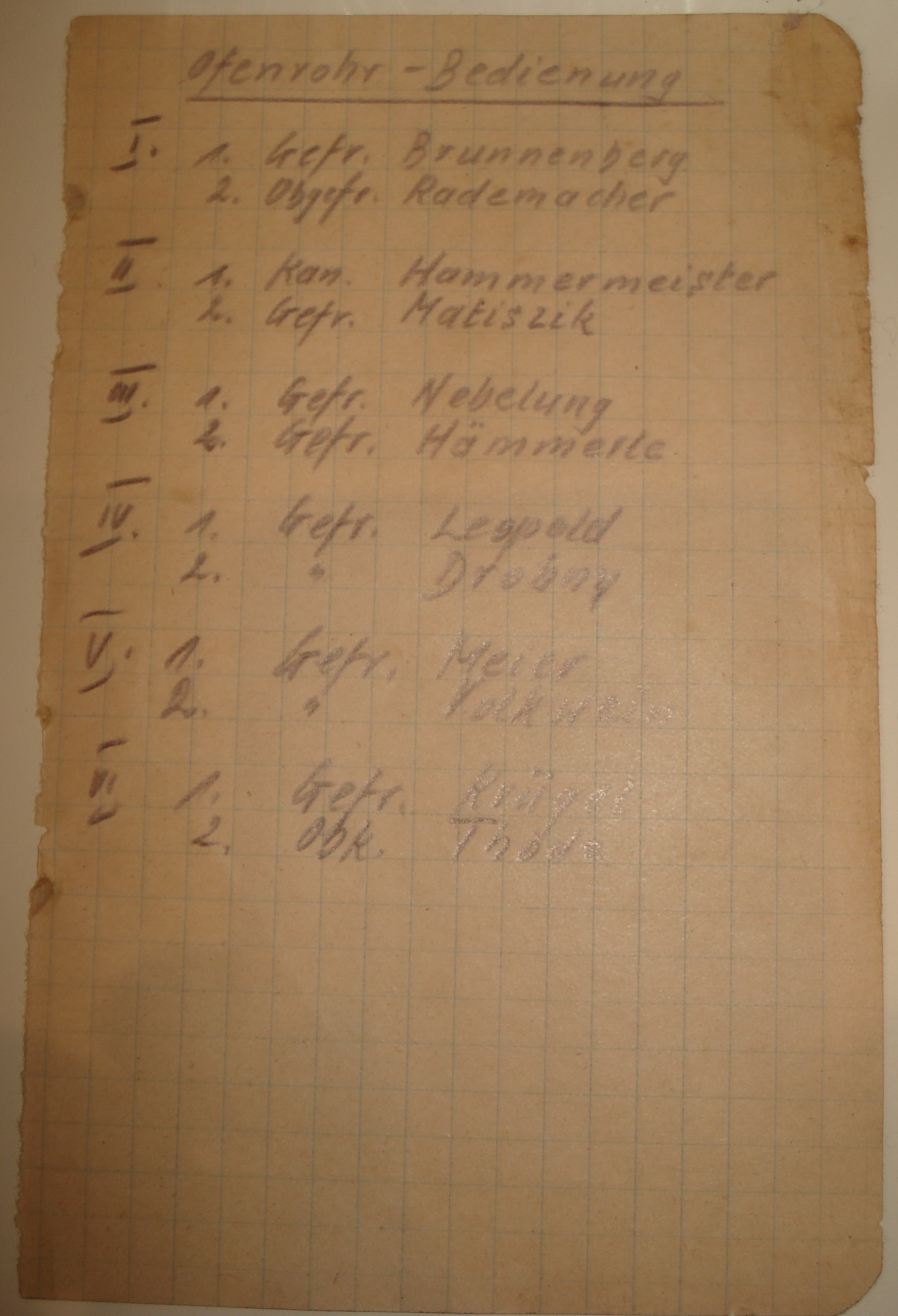
A page from a notebook, handwritten with a pencil. It was discovered in a stack of papers on a fleamarket in Northern Germany last year, and aquired for the net sum of one euro.
This handwritten notebook page doesn't give us much information, apart from the names of soldiers most likely long dead by now. But some information can be extracted. The roster list belongs to a unit with 6
Panzerschrecks (Ofenrohr), listed as I to VI. All armies with some dignity and self respect
will have a Order of battle. All units will be assembled, like a
puzzle, according to a list. And this list will specify the personell,
the tasks and capacities and the material/equipment needed to complete
the specified unit. The Wehrmacht used lists called Kriegsstärke-
und Ausrüstungsnachweisungen. Once a unit was established they kept
records, with the renowned German Gründigkeit, and reported to the
higher echelon the current inventory, losses, resupplies etc. The
leading expert on the German WW2 ORBAT in Norway, Simon Orchard, has
shared the following list! 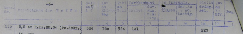 This is the inventory for Armee Abteilung Narvik as of 1. May 1945, 7 days before the war ended. The unit was entitled to 684 pieces of the 8,8 cm R. Pz. BU. 54 (Pz.Schr.).But they had only 360 weapons in use with the troops, and another 101 in their unit arsenal. |
||||||||||||||||||||||||||||||||||||||||||||||||||||||||||||||||||||||||||||||||||||||||||||||||||||||||||||||||||||||||||||||||||||||||||||||||||||||||||||||||||||||||||||||||||||||
| Home | For sale | Site map | Contact information | Guest book | The Panzerschreck Lounge |


