
| Home | For sale | Site map | Contact information | Guest book | The Panzerschreck Lounge |
 Panzerschreck
- The launcher tube Panzerschreck
- The launcher tube
|
|---|
The Stovepipe in details The
main part of the weapon system is the
actual launcher tube, which appears to be just a straight piece of
tubing, but
isn't. The tube is slightly oversized and is actually 9,1 cm but has
three longitudinal indentations that reduces the actual calibre to
8,8cm. The longitudinal indentations will stabilize the rocket; while
at the same time
ensure that
the friction between the rocket and the launcher tube is kept at a
minimum.
This allows for powder residues, dust and dirt to be present to some
extent
without adding too much friction. It would take 1000 rounds (according
to a official document) to wear out
a tube
to a degree where the accuracy got too low and it had to be scrapped.
The user manual D1864/1 has the following to say about the launcher
tube: Ensure
that the tube is empty (from
snow or dirt)
prior to firing. Clean the tube with a makeshift wiper. A
little
dirt does not hurt as rocket has enough play. Holes in the tube (I guess from shrapnel or bullets) does
not hurt when they are turned away from the
shooter. Shoot only from dented or damaged tubes if the shell
can
pass through without any obstructions. (Check: slip a rocket
through manually.) Slight dents can be repaired through
improvisation.
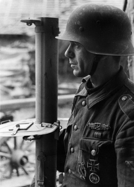
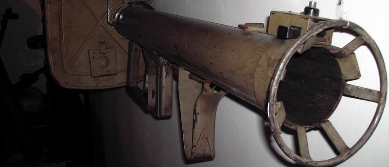
On
the propaganda picture above
one of the longitudinal indentations is clearly visible. The
Panzerschreck has a adjustable rear sight and what appears to
be a
makeshift hand guard.
The muzzle endOne
of the big problems with the Panzerschreck (of course beside the
missing shield) was that the tube was long, and the firer
couldn't always control the muzzle end during movement and sighting.
As a remedy a "Schutzbügel" (safety guard) was mounted under
the
front of the tube. The D1864/5 that was issued on 24. February 1944
gave clear instructions on the mounting of this device for those early
weapons that
didn't have it installed from the factory. The instructions clearly
state that the purpose of the safety guard is to hinder snow or sand
from entering the muzzle when the gunner is moving into a firing
position.
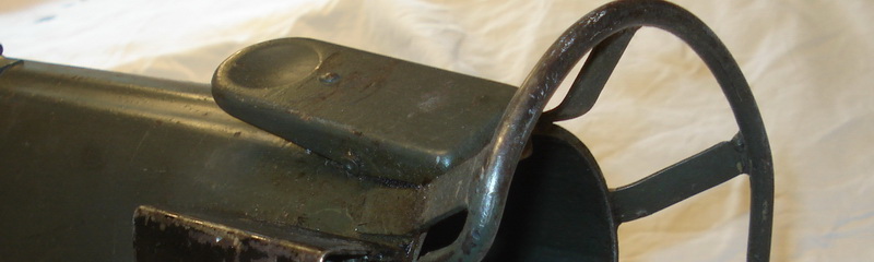
The safety guard should be placed straight behind the front sight, like
it has been done in the picture above. 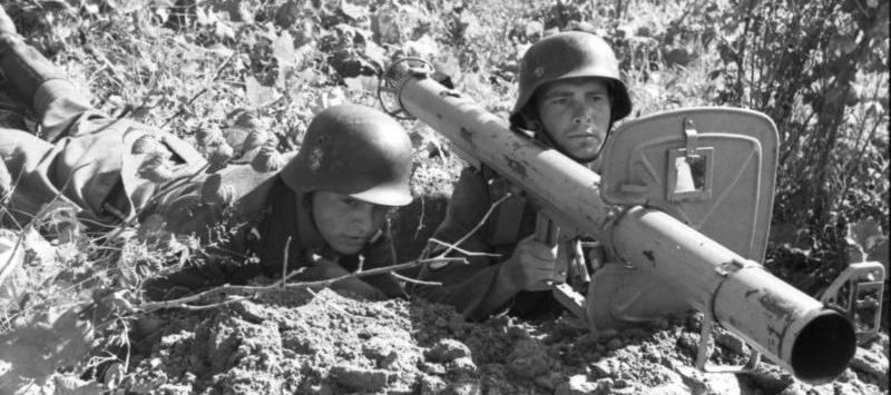 Northern
Russia, September 1944. The Schutzbügel has lost the locking piece and
has moved way too long to the rear. Also note Model I front sight. The
weapon has a Model II rear sight, although not visible in this photo.
A nasty accident could occur without the safety guard and a professional operator. 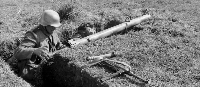 Italy,
April 1944. Note how the firer has placed the muzzle with no safety
guard in the grass. If this was sand he might have ended up in trouble,
but the shot will not be fired, as the scene is staged. Note that the
rocket being loaded still has the transport tape and wooden contact
holder in
place. Also of interest is the late MP40 and a smoke hand rocket.
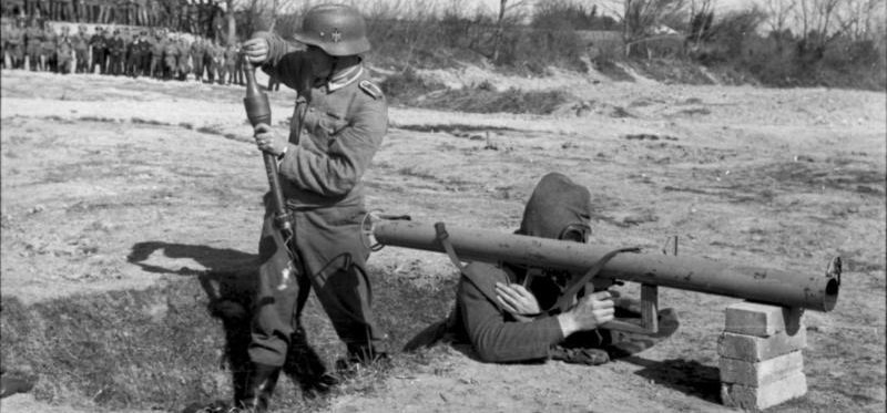
In a publication of the "Von der Front für die Front" dated 6. June 1944 the OKH states that although most of the requests from the front call for a bipod this will not be manufactured for the Panzerschreck. It has been deliberately omitted, since the weight of the weapon would increase, and it would be a hindrance during change of position. The Shutzbügel was not meant to be used as a monopod during firing. Most of the time the protective shield and the trigger guard would be sticking lower and would be used to balance the weapon. 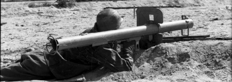 Reichsgebiet
1944. Note how the firer has dug down the shield and placed the
Schutzbügel on a pair of wooden boards to use it as a monopod. He
appears to be wearing a leather jacket and has gloves on to
protect his right hand from burns. No rocket in
the tube.
The sling There
was only one type of sling used on the Panzerschreck family. It was
made of canvas and was adjustable with a friction buckle. The end that
held the friction buckle, as well as the other end that fastened the
sling to the weapon both had a "LUX" clip pressed on. This meant that
the sling was mounted permanently to the weapon, and could not be
replaced by the operator. The weapon had two square rings hinged to the
top of the tube that the sling was mounted on.
 From a demonstration in France, spring 1944. A pile of bricks act as a rest. No gloves have been put on, in violation of the safety requirements. Note the dark web sling. 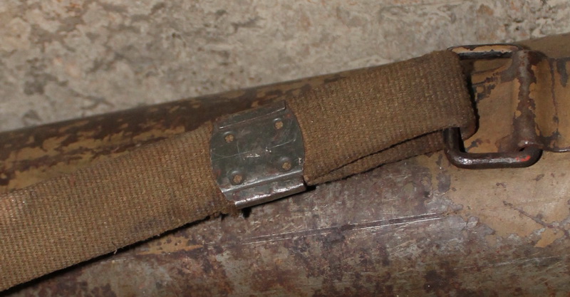 A original web sling with the LUX fastener clip mounted to the rear swivel of a RPzB 54. 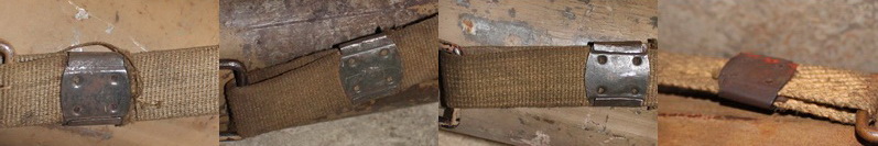 4 different original slings. Note the Ersatz-quality of the last one The shoulder rest and shoulder block The
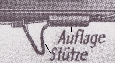
shoulder rest (Stütze) was placed so that the weapon would rest against
the firers shoulder and distribute what recoil there was. In
addition it served as the mounting bracket for the Stoßgenerator that
was welded directly to the front of the shoulder rest. The mission of
the shoulder block (Anlage) was to elevate the tube so that the
sighting line would match the firer's eye-height. In addition it also
concealed the tube with the ignition cable making it less
vulnerable to damage. At least two different profiles differing in
height exists of the Anlage.
 The shoulder rest and block appears to have been manufactured without any modifications from the first prototypes of the RPzB 54 until the end of production. 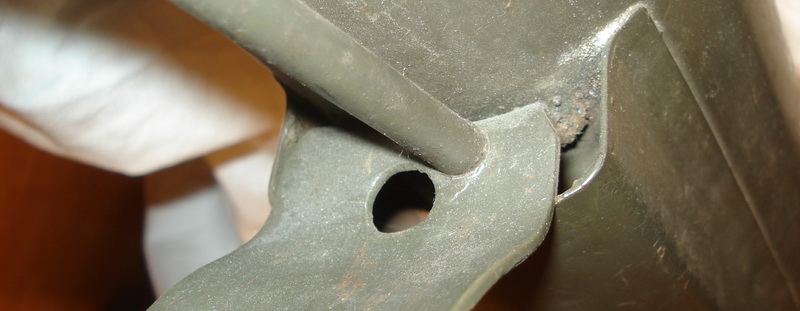 The
picture above show the inside of the shoulder rest, facing backwards.
The metal tube runs from the Stoßgenerator with the electrical wire to
the Steckerbuchse at the end of the tube. It passes through a hole in
the bracket (that is covered here by the tube). The second hole in the
center of the bracket is used for the aligning of the parts during the
welding to the main tube. There is a corresponding hole in front of the
bracket that is covered by the Stoßgenerator and the wire-tube.
 The
picture above shows a RPzB 54/1. The shoulder rest show the two holes
as described for the RPzB 54. When the RPzB 54/1 was designed the
Steckerbuchs was moved to the top of the tube, and the metal tube that
holds the wire was moved from the left side to the right, and the
shoulder block was discontinued. So the hole for the tube was no longer
necessary, but is still there. Note that the improved safety catch has
been applied.
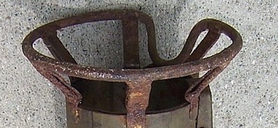
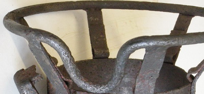
The rear end A slightly larger ring was welded to the outside end of the tube. It held the protective ring, as well as the rocket catch and the connection box. The protective ring was meant to keep objects away from the blast and guide the loading of the rocket. It had a dent to the profile that lead to the connection box. This made it easier for the loader to connect the rocket plug. The design was flawed from the start, as the support struts was welded to the outside of the ring. This left a "step" from the struts and into the tube. And since the rocket was designed with a belt on the middle (also with a "step"), the rocket would snag and get stuck during the loading process. 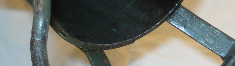 To remedy this the D 1864/1 manual instruct the units how to fix the problem themselves in a very easy way. 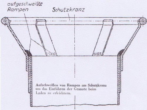 Simply smoothing out the step by welding would do the trick!
With the introduction of the RPzB 54/1 a whole range of varieties appears, but those will be discussed in the RPzB 54/1 section. The rocket catch The
spring loaded
catch
(Sperre) prevented the rocket from falling out of the rear after
it had been inserted. On the
Raketenpanzerbüchse 54 it sat at the 12'o clock position. There were
two models in use. One with a serrated depression and one that was
smooth.
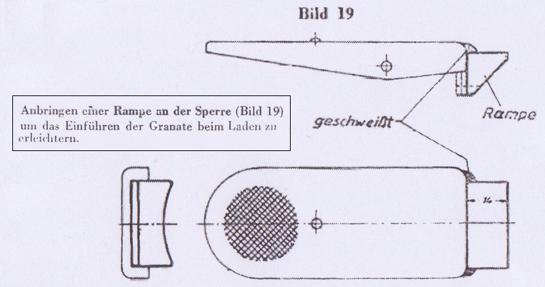
 Again
the design was flawed from the start. Since its only function was to
prevent the rocket from falling out of the rear it made no sense that
the catch had to be pressed down to load the weapon. The remedy for
this was once again very simple. A ramp was welded to the end of
the catch so that it was lifted up when a rocket was pressed
into the tube. Once again the manual D 1864/1 contained a set of clear
instructions, and pointed out that these improvements were developed by
the frontline troops themselves.
 I
haven't managed to find any pictures of this improvement in use or on
any surviving examples. It doesn't appear to have been set in
production at all for the RPzB 54. But the catch on the RPzB 54/1 was
fully redesigned and incorporates this feature.
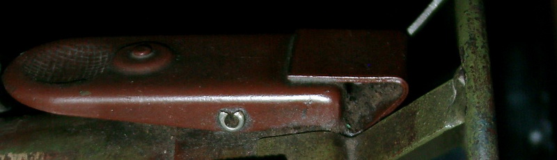 The RPzB 54/1 catch. Note the larger "nipple" that holds the spring in place, as well as the ramp that makes the loading process easier. The connection box 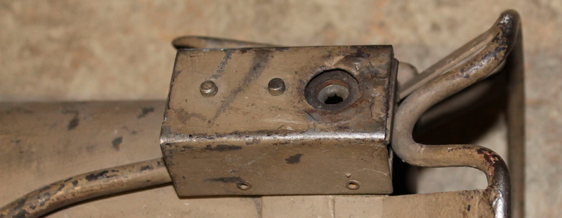 A
metal tube containing a twin wire ran from the Stoßgenerator and was
terminated in the connection box (Steckerbuchs) that was placed at
the 10'o clock position viewed from behind. The box served 3
functions, which
corresponds with the 3 items on the top cover. The front-end pin was a
spring pressured stop bolt (Anschlagbolzen) that would stop the rocket
from going too far in during loading. When the rocket was ignited the
tail ring would force the pin out and continue down the tube. The
second pin (Kontaktbolzen) was also spring pressured (and pointy) and
would ensure that
the rocket was earthed to the tube. This way the
return current
would travel unhindered back to the connection box. One of the wires
from the metal tube running from the Stoßgenerator was
soldered to
the Kontaktbolzen. The second wire was soldered to the female contact
that accepted the corresponding metal pin on the wooden contact holder.
This
procedure is described on the page about the firing system.
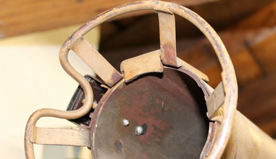
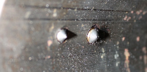 This picture shows the pointy Kontaktbolzen and the Anschlagbolzen on the inside of the tube. The connection
box was not re-designed during the production period of the RPzB 54,
but also had
its problems. "Von der Front für die Front" dated 8. September 1944
had the following text:
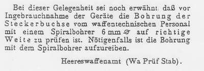 There
must have been a problem with the contact-plug on the ammunition in
regards to the diameter of the hole in the connection box. It states
that weapon technicians should use a drill bit to check that the
diameter is 6mm, and
correct it if necessary.
|
| Home | For sale | Site map | Contact information | Guest book | The Panzerschreck Lounge |