

| Home | For sale | Site map | Contact information | Guest book | Lafette-menu |
 The spring assembly The spring assembly |
|---|
The "why?" The Lafette 34 was fielded in 1936 to fulfill the MG34's role as a heavy machine gun (SMG). The Lafette enabled the gunner to engage targets and lay his fire with accuracy at medium and long ranges. One part that made this possible was the built-in recoil mechanism in the upper part of the Lafette. The old WW1 Schlittenlafette for the Mg08 relied entirely on weight to absorb the recoil of the machine gun, and this made it unnecessary heavy to haul around the battlefield. The new Lafette absorbed the recoil through a recuperator spring and a buffer spring. This way the Lafette could be built much lighter, but still be able to bring home the bacon. The same spring assembly was used on both the Lafette 34 and the Lafette 42. Function 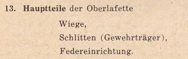 The upper mount consists of the cradle, the frame with the weapon mounts and the recuperator assembly (Federeinrichtung). 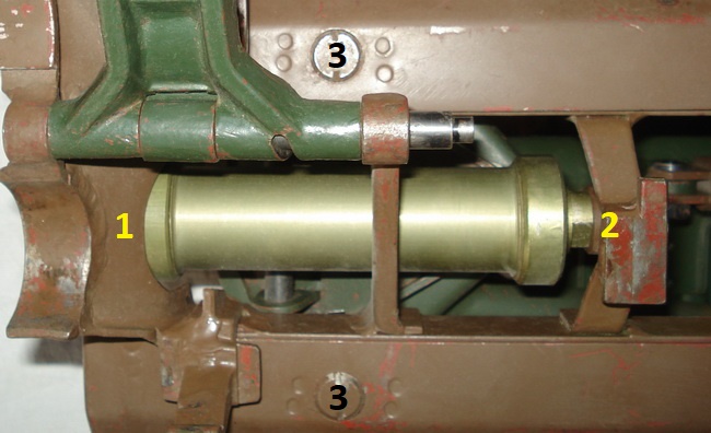 On the Lafette the weapon is mounted on a frame that recoils inside a cradle. The spring assembly is anchored to the cradle at the front (1, but underneath the part it points at), while the rear is attached to the center crossbar of the frame with the weapon mounts (2). The frame rides on 4 rollers (3) that are mounted inside the cradle. The trigger mechanism, the spent cartridge case deflector tray and the weapon mounts rides on the frame. 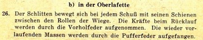 The functioning of the recuperator and buffer mechanism as explained in the manual D 124/2 MG34 Teil 2 MGLafette 34 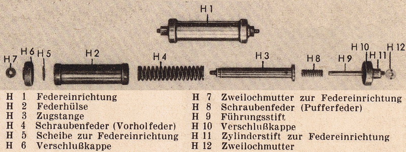 When the gun is fired the recoil force will send the frame backwards. But the spring assembly is anchored to the front of the cradle (H12), so the spring housing will stay put. The rear end of the spring assembly (H7) is anchored to the recoiling frame, and the recoiling force will pull the piston rod (H3) rearwards compressing the recuperator spring (H4) and storing the recoil energy. With the recoil energy spent, the stored energy will force the recoiling frame forward again. The buffer spring (H8) will stop the forward movement and prevent the moving frame from slamming into the cradle. Removing and installing the recuperator assembly The spring assembly is attached to the frame and cradle by a special nut. The nut is called a "Zweilochmutter", which can be translated to a "two hole nut". 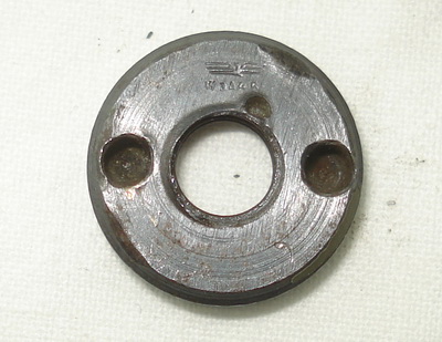 The Zweilochmutter. Note the punch mark close to the threads that was applied at the factory to prevent the nut from coming undone. The part was approved and stamped by a Waffenamt Inspector. The front and rear nut are, of course (!), different. The front nut is slimmer and has a beveled edge on the side that has the holes. This gives it a lower profile and less chance of snagging. The rear nut is thicker and has a beveled edge on the opposite side of the holes, as this side of the nut resides in a countersunk hole in the frame. Unscrewing the Zweilochmutter requires a special tool, the "Zapfenschlüssel zur Zweilochmutter 13 mm". A "pin wrench". 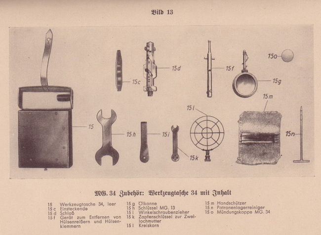 The contents of the MG gunner's tool pouch. Note 15K: Zapfenschlüssel zur Zweilochmutter This tool was standard issue in the gunners kit, but was only of use to those that had a Lafette. It enabled the gunner to tighten the Zweilochmutter on the spring assembly and adjust the sight base on the Lafette. 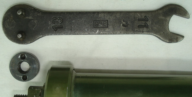 The pin wrench. The number "13" refers to the actual width between the two pins, which is 13 mm (millimeter). 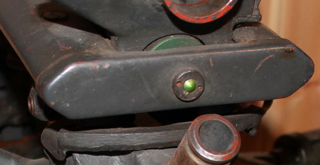 The front nut can be unscrewed easily, as it is fully exposed. The whole body of the spring assembly can easily be held by the hand to stop it from rotating with the nut. When removed the whole frame can be slid rearwards to "maximum recoil" is obtained. This makes it easier to remove the rear nut. 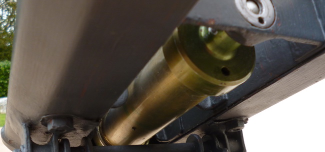 The rear nut is situated in a countersunk hole, and due to the frame on each side the wrench can only by rotated a quarter of a turn each time. For this reason the tool has two sets of pins, one set on each side that is positioned crosswise to each other. 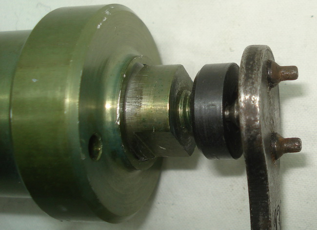 The rear nut is attached to the piston rod, and this will rotate freely with the nut unless arrested. This can be achieved with a 19mm (3/4 inch) spanner, as the end of the piston rod has two flat surfaces. These can only be accessed from below. With the rear nut removed the spring assembly can be slid slightly forward and then removed by letting it fall down. 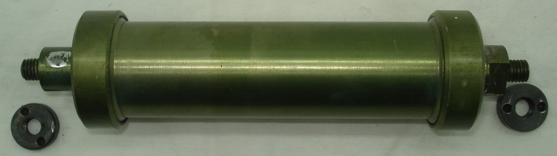 It is installed by reversing the steps. 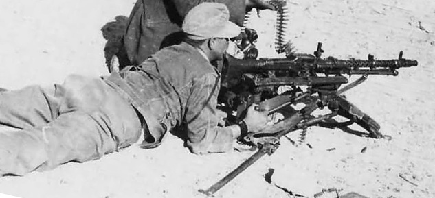 Maintenance The spring assembly was not serviced by the user, apart from securing the nuts and normal cleaning. Taking it apart requires yet another special tool, the "Zapfenschlüssel für Zweilochmutter 30 mm". 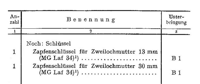 This tool was found in the armorer's small toolbox, the "Kleiner Waffenmeisterwerkzeugkasten für MG und Handwaffen". The same box also contained the Zapfenschlüssel zur Zweilochmutter 13 mm, as the armorer didn't have a MG accessory pouch. 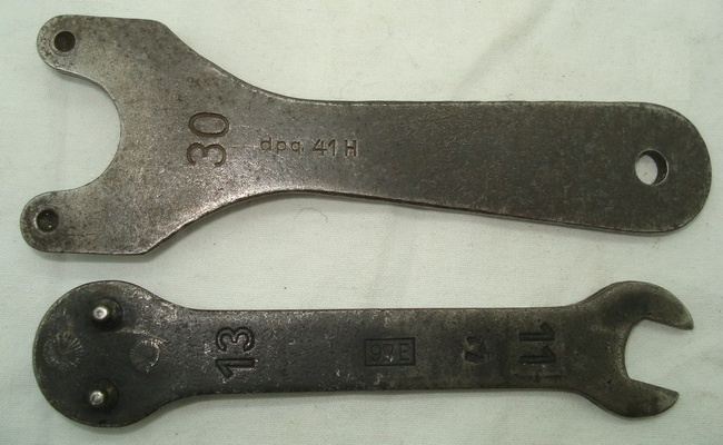 The Zapfenschlüssel zur Zweilochmutter 13 mm and the Zapfenschlüssel zur Zweilochmutter 30 mm 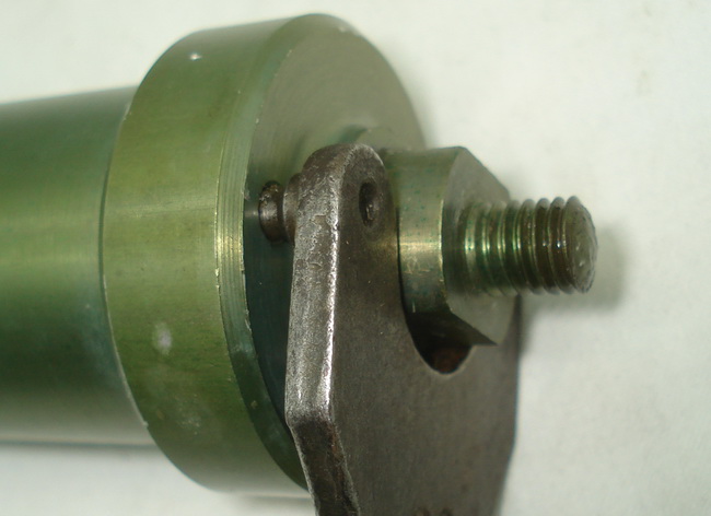 With this tool the end cap can be removed and the internals inspected. 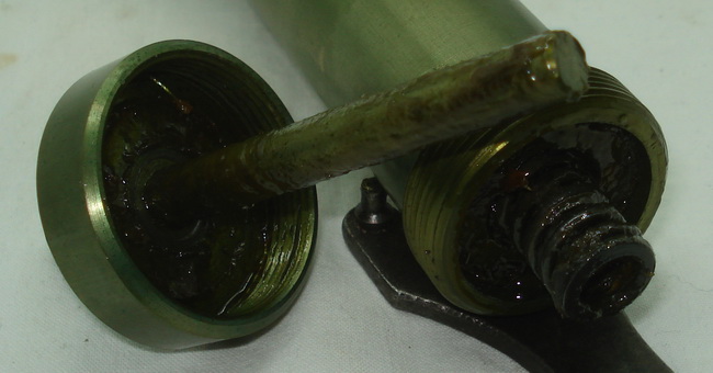 The endcap from the front end has been removed. The guiding rod runs inside the buffer spring and the piston rod (just visible, with the buffer spring slightly pulled out of it). 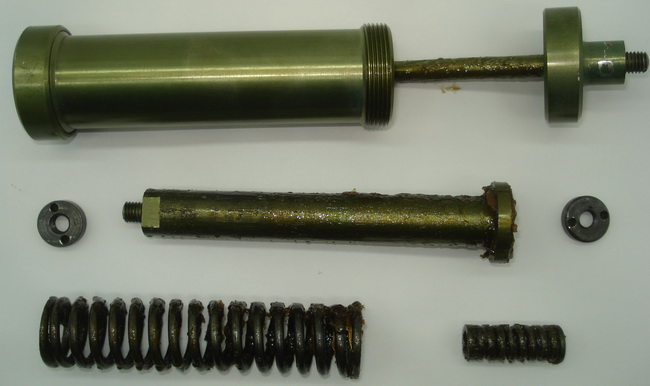 According to the manual, the whole unit should be greased well The early manual for the MG34 Lafette doesn't mention much about the maintenance of the spring assembly. But the repair manual for the MG42 has a short section about maintenance for the Lafette 42. 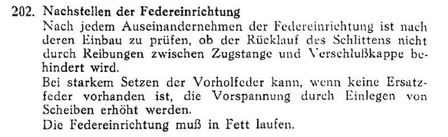 It is stressed that each time the spring assembly has been taken apart it should be inspected when reassembled and installed. Especially check for extra friction between the piston rod and the housing. If the recuperator spring is much worn, and a new spring can't be supplied, the tension can be increased by adding discs behind the spring. The spring assembly must be well greased inside.  Development During the production period of the Lafette the spring assembly didn't change its function or basic design. But as the war progressed the need to preserve lightweight metals for the aircraft industry increased. The spring assembly housing and piston rod was made out of Duralumin until 1943, when the steel version came into production. 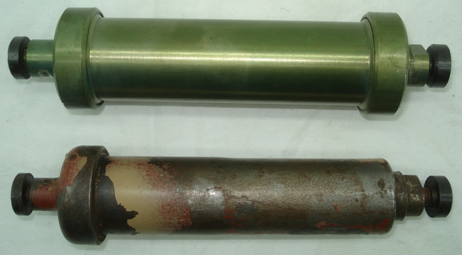 The steel version was slightly slimmer, but the weight of the unit increased with 25% with the change of materials. The end cap retained the same size as the Duralumin model, so the Zapfenschlüssel zur Zweilochmutter 30 mm was still used to take it apart. Markings The standard tube has no marking at all. The only tube encountered with a WaA I have ever seen, or heard of, is pictured below. It would rate as "an exception". The only parts normally found with markings are the Zweilochmutter as described above. 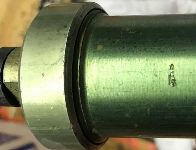 (Picture courtesy of Brian Dolgner)  Let's grab the Lafette and move forward! |
| Home | For sale | Site map | Contact information | Guest book | Lafette-menu |